Maybe they do their testing in a special laboratory on the Antarktis - during the winter time16pin TPA311x LOL 😂
Some vendors say this particular board is a “copy”
US $3.61 5% Off | Copy TPA3116D2 Dual-channel Stereo High Power Digital Audio Power Amplifier Board 2*120W XH-M543
https://a.aliexpress.com/_mth7X8O
120W?
")
xrk16pin TPA311x LOL 😂
Some vendors say this particular board is a “copy”
US $3.61 5% Off | Copy TPA3116D2 Dual-channel Stereo High Power Digital Audio Power Amplifier Board 2*120W XH-M543
https://a.aliexpress.com/_mth7X8O
120W?
I'm seeking in Aliexpress about 2 hours trying to investigate .
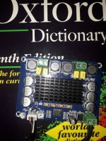
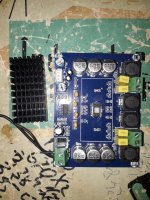
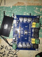
I think "kaisaya" only have the real "thing" (but cost 12,98 euro) + the company on the att photo and the only way to distinguish from the fakes is that the heat sink is attached to the chip/board with 2 screws. The head of the screws are from the back side of the board.
Elias
Last edited:
So mine's identical to the bad one...but why yours have the vias for cooling also through the pcb if it's 3116 and not 3118?
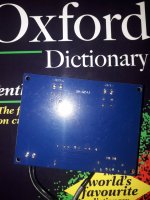
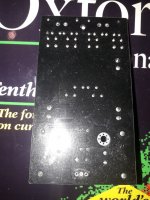
I have a true 3116 with a much smaller heatsink and you can see it has no cooling vias underneath the chip.
I have a true 3116 with a much smaller heatsink and you can see it has no cooling vias underneath the chip.
Attachments
Maybe. But nobody refunds your wasted time.Aliexpress is pretty good with refunds or at least partial refunds if a vendor claims genuine and they are not.
Mine's bought from a third party unfortunately...and while I do have 8 months warranty left, I need to destroy the thing in order to prove is the wrong thing...which makes me lose the warranty...
My only consolation is that it ouputs something...paid 20 bucks on it...Not a big loss...At least the real one I got as a gift.
My only consolation is that it ouputs something...paid 20 bucks on it...Not a big loss...At least the real one I got as a gift.
Nor the disappointment you fill + more than a month waiting for the replacement. In my case, I have received the board more than 2 months ago, so I lost the opportunity for refundMaybe. But nobody refunds your wasted time.
Elias
Can anyone tell if this kit is legit?
https://www.fruugo.ro/tpa3116d2-min...MI646Cu9bU_AIVDtPtCh33lgFFEAkYByABEgJGT_D_BwE
https://www.fruugo.ro/tpa3116d2-min...MI646Cu9bU_AIVDtPtCh33lgFFEAkYByABEgJGT_D_BwE
Works Need a heatsink - pay attention to the high SMD details. No output LC filters Source of strong radio interference on the MV. Price for Aliexpress $2.Model XH-M562. https://aliexpress.ru/item/10050049...92.534681895.1674171696-1035880644.1673436771
Need a heatsink - pay attention to the high SMD details. No output LC filters Source of strong radio interference on the MV. Price for Aliexpress $2.Model XH-M562. https://aliexpress.ru/item/10050049...92.534681895.1674171696-1035880644.1673436771
Last edited:
Apparently mine's not fake even though it has no screws.Nor the disappointment you fill + more than a month waiting for the replacement. In my case, I have received the board more than 2 months ago, so I lost the opportunity for refund
Elias
Attachments
I am pretty sure that ALL boards which sells on Ali and Ebay are Chinese copies. Otherwise they couldn't be sold for a half of original chip price.
But nevertheless .... they are not bad at all.
More important:
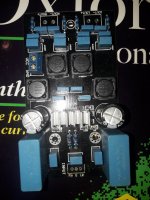
There are different configurations of output filters on those boards. Most of the time you will see 33 uH output chokes and 0.68uF capacitors, like here:

I have been measuring those and in my opinion they are only good for 8 Ohm speakers, if you need a full range amp. Because you will get a significant roll off soon after 10kHz, when using 4 Ohms. I didn`t even bother to try with 2 Ohm (and I don`t have any as they are usually subs for car stereo).
But if you need it for a sub amp it wil be OK, obviously...
Sometimes you will find 10uH and 1uF configuration:

(I have ordered 2 of these but I am still waiting for them... hopefully they will be better at 4 Ohm).
I also had version of 10uH with 0,47uF but I mistakely burned it before I had a chance to measure it
Factory datasheet suggests 10uH and 0.68uF (or 1uF, depending on speaker resistance).
https://www.ti.com/lit/ds/symlink/t...98886&ref_url=https%3A%2F%2Fwww.google.com%2F
What are your opinions or experiences about that? Maybe someone can share some knowledge?
BTW, I am interested only in mono version. Since they are so dirt cheap it makes sense to me to buy 2 mono items (already bridged) and thus build a stereo amp. The power, distortion and thermal dissipation characteristics are for sure better on two mono version compared to single stereo one.
But nevertheless .... they are not bad at all.
More important:
There are different configurations of output filters on those boards. Most of the time you will see 33 uH output chokes and 0.68uF capacitors, like here:
I have been measuring those and in my opinion they are only good for 8 Ohm speakers, if you need a full range amp. Because you will get a significant roll off soon after 10kHz, when using 4 Ohms. I didn`t even bother to try with 2 Ohm (and I don`t have any as they are usually subs for car stereo).
But if you need it for a sub amp it wil be OK, obviously...
Sometimes you will find 10uH and 1uF configuration:
(I have ordered 2 of these but I am still waiting for them... hopefully they will be better at 4 Ohm).
I also had version of 10uH with 0,47uF but I mistakely burned it before I had a chance to measure it
Factory datasheet suggests 10uH and 0.68uF (or 1uF, depending on speaker resistance).
https://www.ti.com/lit/ds/symlink/t...98886&ref_url=https%3A%2F%2Fwww.google.com%2F
What are your opinions or experiences about that? Maybe someone can share some knowledge?
BTW, I am interested only in mono version. Since they are so dirt cheap it makes sense to me to buy 2 mono items (already bridged) and thus build a stereo amp. The power, distortion and thermal dissipation characteristics are for sure better on two mono version compared to single stereo one.
I'm trying to follow CyberPits XH-543 mod plan items 1,2,6,7.
I'm struggling to understand what is done to R14 and R18. The modified schematic says OR, and R12 and R16 say NOP, which I assume means remove them.
Also I have a dead XH-543 that had a glued down heatsink and has 4 1uF caps right infront of the tL074 chip. I was hoping there might be a 100k SMD resistor on it somewhere I can use for the R3 and there was on the R3
Could anybody help me with this stuff?
Last edited:
0R is a convention to say that it is a zero ohm resistor (aka bypass wire). R12 and R14 are changed to be open.
His change just makes the first opamp a unity gain buffer and bypasses the second.
This has the advantage of buffering the input signal and giving it a very high input impedance.
In my testing I felt that the opamp was a fake on the board I was working with so I bypassed it completely. I also ended up lowering the gain down to 20db. I set them to 26db at first but found that the board still had a lot of hiss and it was much improved at the lowest 20db setting. I have a preamp in front of my board anyway so the on board preamp is not useful to me. I did increase the input decoupling cap to 2uF by stacking an additional capacitor on the positive and negative inputs (C1/C2 and C3/C4) on one baord to improve the low frequency response. I did this when I had it set to the higher gain but it is no longer necessary at the 20db setting.
I posted pictures previously on how to just bypass the on board preamp with solder balls which accompishes almost the same thing just without buffering. It is very easy and it makes this board much more like the bridged mono XH-M542 boards that have no opamps that I am using for L/R/C along with the 543 board for surround channels in my custom 5.1 receiver (5.1 decoder with preamp and amplifiers)
-Rich
Last edited:
This guy made the diagram I followed.
You can also read rbryantaz' comment like 3 comments above.
I'm curious about your opinion. Why is it a bad idea? What don't you like about bypassing one opamp and converting the other to a unity gain buffer, thereby reducing gain and crosstalk between the channels?
You can also read rbryantaz' comment like 3 comments above.
I'm curious about your opinion. Why is it a bad idea? What don't you like about bypassing one opamp and converting the other to a unity gain buffer, thereby reducing gain and crosstalk between the channels?
- Home
- Amplifiers
- Class D
- TPA3116D2 Amp