What are people using to get 21V? It's not exactly a standard PSU value, so I reckon a DC/DC converter or adjustable PSU? I'm on eBay now, looking to buy.
Many PSUs have an adjustable output voltage.
Amplifier Board TPA3116 Class D 2X50W or 1x100W Stereo or Full PBTL | eBayI still see it listed on ebay by audiobah - link
What are the advantages of the "PBTL"-board? I'm looking through the thread, but can't find a concise answer.
Are they directly adjustable? I'm not familiar with this, unfortunately.i use a 24V mean well adjusted to 20V.
Green board still on ebay - Amplifier Board TPA3116 Class D 2X50W or 1x100W Stereo or Full PBTL | eBay
Excellent. I have a few comments in blue.
I currently have defined the following feature set
1) 3.5mm jack for single ended input. What if you want to use balanced (differential) inputs in the future?
2) Volume control May I suggest an option to bypass it?
3) Quick connect bare wire speaker terminals
4) All parts from Mouser/Digi-Key except that odd ball heatsink that TI has spec'd in, for which I will find an alternative method if not available.
5) Fusing/reverse polarity/over-voltage protection Typically easily done and with the lowest loss by an n-channel mosfet, a zener diode, a resistor, and a ptc
6) Standard 2.1/2.5mm pin power jack Typically limited to 5A max so will technically not be able to handle peak load
7) Standard Aluminum Hammond Instrument case No need for heat sink in that case (pun intended), just thermally connect either the chip (with a 3116) or the PCB (with a 3118) to the case
8) Many stuffing, configuration options, important ones are set by jumpers.
Last edited:
I still see it listed on ebay by audiobah - link
I swear it wasn't there yesterday...
Hello TPA311x enthusiasts,
I am working on my own design for the fun of it. Any suggestions as to configuration, ideas are welcome, to make it that much better. First version will be 2.0 (one chip), similar to the TPA3116 eval pcb but with my refinements. As with all my designs, I do it firstly for myself, as a learning experience. If a market develops, great, if not, I enjoy the fruits of my labour. I usually like to make a complete stereo with radio etc but in this case I can see this unit being used as a amp for iPod or other portable devices and as your computer desk amplifier as well. I use am currently using a TPA3110D2 in my portable radio/media player and thus am very impressed with this TI technology.
Looks great! I'm not into the technical side of things. But aren't the volume pot and input jack placed too close to eachother (considering a volume knob might be placed and some 3,5 mm jacks can be quite thick)?
Hi Saturnus, thx for your feed back.
1) Funny how I had it originally like the eval pcb (separate RCA) then re-considered why do it, this none standard way. If you look at the DS, it does not show any product diff/improvements in the bal i/p config. Changed it to just use the 3.5mm only.
Balanced input. It is how much % of the market? I have no balanced gear, do you?") Other than my Amber audio test set. Properly done, it should be done with a XLR, as that is what the cabling would be used to make it compatible with existing gear. I do understand that it can be helpful it certain situations. The TI eval used RC'A's as balanced connectors to be cheap. This requires a special cable to be made as well.
Other than my Amber audio test set. Properly done, it should be done with a XLR, as that is what the cabling would be used to make it compatible with existing gear. I do understand that it can be helpful it certain situations. The TI eval used RC'A's as balanced connectors to be cheap. This requires a special cable to be made as well.
It is a simple wiring mod, if someone wants a XLR and they want to pay for it. Also modified bezel machining as well.
2) Sure, just don't stuff the part and add two wire jumpers. One less hole to drill for me
It is like the gain setting, what should it be set to by default? I choose min. gain, (as I think it gives highest performance) but that depends on your source. The VR is a good option, as it would work great with a CD player, that has lots of o/p. I have chosen the Bourns PTD902-2015KA104 pot due to availability and mfg quality.
5) I do not want to make the protection mechanism to expensive, as it is, it is optional, if properly installed, it should never activate. Your method is done distructive but adds cost. Is the customer will to pay for this improvement is the big ? I believe that there should be limited protection for gross faults. A fuse, 5W zener adds OVP, RPP, PS SSP for a very small cost.
6) Yes, I understand the limits of the crappy DC power jack. The problem is, that it is the defacto standard. Having a big storage ecap will help with current demand in transient conditions. I will use the good quality Switchcraft silver plated connectors. Do you have a suggestion as to an alternative means.
7) Yup, as simple AL bracket/HS to lay across the device slug and then fasten to the chassis. A 1mm spacer, for the bracket/HS
1) Funny how I had it originally like the eval pcb (separate RCA) then re-considered why do it, this none standard way. If you look at the DS, it does not show any product diff/improvements in the bal i/p config. Changed it to just use the 3.5mm only.
Balanced input. It is how much % of the market? I have no balanced gear, do you?
Other than my Amber audio test set. Properly done, it should be done with a XLR, as that is what the cabling would be used to make it compatible with existing gear. I do understand that it can be helpful it certain situations. The TI eval used RC'A's as balanced connectors to be cheap. This requires a special cable to be made as well. It is a simple wiring mod, if someone wants a XLR and they want to pay for it. Also modified bezel machining as well.
2) Sure, just don't stuff the part and add two wire jumpers. One less hole to drill for me
It is like the gain setting, what should it be set to by default? I choose min. gain, (as I think it gives highest performance) but that depends on your source. The VR is a good option, as it would work great with a CD player, that has lots of o/p. I have chosen the Bourns PTD902-2015KA104 pot due to availability and mfg quality.
5) I do not want to make the protection mechanism to expensive, as it is, it is optional, if properly installed, it should never activate. Your method is done distructive but adds cost. Is the customer will to pay for this improvement is the big ? I believe that there should be limited protection for gross faults. A fuse, 5W zener adds OVP, RPP, PS SSP for a very small cost.
6) Yes, I understand the limits of the crappy DC power jack. The problem is, that it is the defacto standard. Having a big storage ecap will help with current demand in transient conditions. I will use the good quality Switchcraft silver plated connectors. Do you have a suggestion as to an alternative means.
7) Yup, as simple AL bracket/HS to lay across the device slug and then fasten to the chassis. A 1mm spacer, for the bracket/HS
1) well, you can still use minijack. Just make the ground connection close to the inputs and clearly marked so if you use balanced signals you just cut the ground connection and use an XLR to minijack or jack to minijack cable. Problem solved with the option open for balanced use.
2) if you use the lowest gain setting you also cut away perhaps the biggest market, ie. the portable audio market as a head phone output of an mp3 player or smart phone doesn't drive the input high enough on the lowest gain setting
5) a fuse, a fuse holder or a 5W zener are all in themselves and by themselves more expensive and more complicated to use than all the 4 parts I listed. Not to mention with a far greater power loss and parts that have to be replaced on a false tripping where the n-channel FET solution is self-resetting and failsafe.
6) Yup. Molex mini Fit Jr 4 pin connector.
1) 3.5mm stereo Min-jack has tip(L),ring(R),shield(Ground return common for L&R). 2 separate stereo min-jacks would work as you describe.
2) Okay, so what do you suggest for a default gain setting 20,26,32,36? Will then need a bigger footprint for TH film (15mmLS) 3.3/4.7/6.8/10uF coupling cap as well, if you want the same LF response. I will do this mod.
3) Can you get me a ckt and BOM together as a comparision. I have pcb area available to add a alternative protection method, as you describe.
an n-channel mosfet, a zener diode, a resistor, and a ptc.
My soultion
Fuse, Littlefuse 0251005.MXL, 1: $0.696
Zener, MCC 833-SMBJ5363B-TP 1: $0.799
A optional fuse holder just adds more costs, but I will add a 5x20mm fuse and holder option as well.
If I make the fuse big enough, 5-7A, I do not think that I will not get any nuisance tripping.
6) need right angle. Needs to stick out through the bezel as this is the customer DC interface now. I could add it as an alternative footprint, just for you
9A contact rating for 5569 series, so only really need two contact positions. Molex 39-30-1020 is a good alternative or option. Now I can sell assembled cables as well
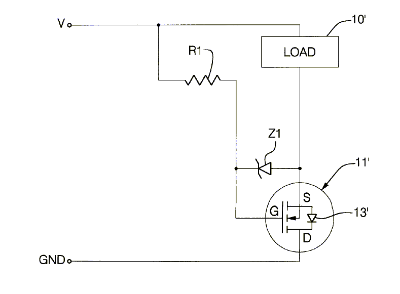
Well, the chip itself has over voltage, under voltage, short circuit, over current, over temperature, and dc offset protection so I can't actually see a need for those externally as well. So the FET and resistor for reverse polarity protection is all that is needed really. The zener is optional, yes.
Last edited:
Amplifier Board TPA3116 Class D 2X50W or 1x100W Stereo or Full PBTL | eBay
What are the advantages of the "PBTL"-board? I'm looking through the thread, but can't find a concise answer.
...
Data sheets are where the information is located...good place to start actually.
Does not copy and paste well but here is the info:
Minimum / Nominal loads
(BTL) Output filter: L = 10 μH, C = 680 nF
TPA3116D2, TPA3118D2 3.2 / 4 Ω
TPA3130D2 5.6 / 8 Ω
(Two channels per IC)
(PBTL) Output filter: L = 10 μH, C = 1 μF
TPA3116D2, TPA3118D2 1.6 Ω
TPA3130D2 3.2 /4 Ω
(One channel per IC)
What are the advantages of the "PBTL"-board? I'm looking through the thread, but can't find a concise answer.
Putting it into practical terms with a PBTL board you will have twice the power and also the ability to drive loads bellow the 2 Ohms mark. For example :
TPA3116 in PBTL with 25V supply + 2 Ohms speakers = 120W at 1% THD
If you have that speaker design with great alignment that has been put aside because of the resulting low load then the PBTL board is great news for you
Or if you have some good 4 ohm drivers lying around and want to run them doubled up as 2 ohm loads for double the punch, this will be great news too.
Btw, have you guys noticed that this thread is taking off like wildfire? It was at 5000 views like 4 months ago? This is the "NEW" TA2024 lepai thread with many of the same experienced hands now pitching in - it is great to see that we are getting deeper into the nitty gritty uses/mods for this amp.
Btw, have you guys noticed that this thread is taking off like wildfire? It was at 5000 views like 4 months ago? This is the "NEW" TA2024 lepai thread with many of the same experienced hands now pitching in - it is great to see that we are getting deeper into the nitty gritty uses/mods for this amp.
- Home
- Amplifiers
- Class D
- TPA3116D2 Amp