My filter & three of £3.37 amp modules arrived today, much sooner than I was expecting! The thermal adhesive on one of the amp modules failed & the heatsink was loose, so I'll have to reattach that. The solid capacitors are labelled 'Elna' but somehow I doubt they're legit considering the price...
The Sanwu ones have got two screws holding the heatsink on but they are another couple of quid. The screw terminals for audio input look more convenient on these though.
Lots of hiss on these, even after removing the trim on the inputSuppose I shouldn't've expected much better for the price of a beer, are the more expensive units better in this regard?
If you've got one of those 2.1 pre-amp boards on the way, they help a lot. Also knocking the gain down to 20dB. Have a look at those resistors under the heatsink. There's one on the bottom left and three on the right. If you have a look at section 7.3.1 in the datasheet http://www.ti.com/lit/ds/symlink/tpa3118d2.pdf, see if you can find out what the gain is set to. I had to remove one resistor to get 20dB gain on the Sanwu ones. If you look very closely at the resistors they might have three digits for the values.
Edit: ah you have got the filter board, have you tried that yet?
Last edited:
Lots of hiss on these, even after removing the trim on the input
Don't worry, those with a TPA3116 board are very familiar with this hiss. It will be removed. chopchop will explain how.
Price of a beer? enter a good restaurant in Stavanger (NO) and order a quality beer - it is that beer or a complete stereo set.
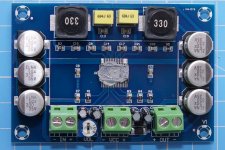
I've not tried the filter board yet, as I wanted to test the boards 'unadulterated' first! Luckily the SMD resistors do have legible markings on them, but it's too late where I am to puzzle out which one is which in relation to the datasheet tonight
It looks like 75k (R3 on this PCB, known as R2 on the datasheet) and 47k (R4 on this PCB, known as R1 on the datasheet), which is 36dB gain in Master mode. If you remove the 75k one it should work as 20dB Master.
This board doesn't look too bad to mod, there's a lot more room between the SMD resistors compared to the Sanwu one. A quick dab with my soldering iron got the SMD resistor off. Soldering another resistor on the Sanwu would be far trickier, but on this board you've got it looks easier. No need for any resistors to go on if 20dB is alright though.
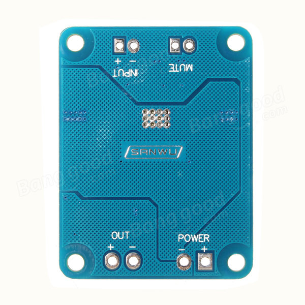
I would say try the filter board first. Should be easy to do with the bare ends from the filter board connector cables into the screw terminals. I had to solder mine onto the underside of the Sanwu PCB.
Hope it's OK to ask this here. I plan on using one of these boards, either TPA3116 or TPA3118 (without heatsink) in PBTL mono mode in a guitar amp. So the question is, if I use overdrive or distortion effects, will the maximum output power be increased because the input signal is already clipped?
So for example, at 20V, 4ohms speaker, a sine wave in the input, I can get up to 40W with 1% THD. But what if the input signal is clipped and therefore the RMS voltage is higher? Do I get more watts in the output with 1% THD or will the TPA chip produce extra distortion?
Thanks
So for example, at 20V, 4ohms speaker, a sine wave in the input, I can get up to 40W with 1% THD. But what if the input signal is clipped and therefore the RMS voltage is higher? Do I get more watts in the output with 1% THD or will the TPA chip produce extra distortion?
Thanks
In principle yes.
As long as you do not drive the amplifier to its limits, no. It is just another signal to amplify - the amplifier doesn't care about what signal it is.
When you get to the limits of the amplifier, the distortion shoot up. But, you may not notice because it is already a distorted input signal. So, you may accept to use the amplifier at for instance 10% THD.
If you have a normal (undistorted) signal and you get above 1% THD, you will hear that the amplifier does no longer sound pleasant so you use it to around 1% THD as a maximum. In principle, with an undistorted input signal, you could drive the amplifier to 10% THD (firm clipping) and you would get about the same output power as if you used a distorted input signal.
It is a somewhat hypothetical situation.
To try to reply to your second question: as long as the amplifier is used below its clipping limits, the amplifier add little distortion to the signal disregarding if it is a distorted signal or not. When you pass the clipping limits of the amplifier, it starts adding important distortion to the signal but you may not hear it if it is already a distorted signal.
You talk about 1% THD with a distorted input signal. This is an inherent contradiction because the THD is defined as harmonics that are added to an undistorted signal. THD is defined for a fixed amplitude, undistorted signal. Soon somebody will tell us that it is nonsense to talk about THD with a heavily distorted input signal.
I hope you get the qualitative gist of my reply.
Last edited:
In principle yes.
...
I hope you get the qualitative gist of my reply.
Mercy
As long as you do not drive the amplifier to its limits, no. It is just another signal to amplify - the amplifier doesn't care about what signal it is.
When you get to the limits of the amplifier, the distortion shoot up. But, you may not notice because it is already a distorted input signal. So, you may accept to use the amplifier at for instance 10% THD. If you have a normal (undistorted) signal and you get above 1% THD, you will hear that the amplifier does no longer sound pleasant so you use it to around 1% THD as a maximum. In principle, with an undistorted input signal, you could drive the amplifier to 10% THD (firm clipping) and you would get about the same output power as if you used a distorted input signal.
It is a somewhat hypothetical situation.
To try to reply to your second question: as long as the amplifier is used below its clipping limits, the amplifier add little distortion to the signal disregarding if it is a distorted signal or not. When you pass the clipping limits of the amplifier, it starts adding important distortion to the signal but you may not hear it if it is already a distorted signal.
Aha, I see, so the limit of the amplifier is determined by the rail swing (-20V to +20V in my case), not the raw output power. Understood.
You talk about 1% THD with a distorted input signal. This is an inherent contradiction because the THD is defined as harmonics that are added to an undistorted signal. THD is defined for a fixed amplitude, undistorted signal. Soon somebody will tell us that it is nonsense to talk about THD with a heavily distorted input signal.
Thanks for the clarification. So we could say instead that the THD at the output is a 1% higher than at the input, with both being significantly larger than 1%, right?
So that seems to suggest I need to plan for extra heat dissipation headroom and should probably avoid the TPA3118. Running the heat-sinked TPA3116 at 4ohms minimum should be alright for my purposes. I'm looking into this one, because it's cheap and comes with screws in the heat sink. Does it look like a decent option to you guys?
DC 12V-24V TPA3116 Mono Channel Digital Power Audio Amplifier Board BTL Out 100W 192090101108 | eBay
In fear of the theoretical guys arriving in a minute to slap our fingers, ".... the THD at the output is a 1% higher than at the input...." is probably not theoretically correct because the input signal includes a multitude of frequencies to which is added different levels of harmonics by the amplifier. I understand what is your meaning and I agree with the principle.
Like you propose, I would go for a PBTL configured TPA3116 board.
Last edited:
dazzamps, have you tried your guitar amp yet? just bought a "Nobsound" NS-01G for that purpose, which I think is TPA3116 based. Wondering how it will stand up to heavy use.... found a pic of its guts on the net, very tiny heatsink... Only got AUD45 to loose, so I'll hook it up this week end & give it hell....
dazzamps, have you tried your guitar amp yet? just bought a "Nobsound" NS-01G for that purpose, which I think is TPA3116 based. Wondering how it will stand up to heavy use.... found a pic of its guts on the net, very tiny heatsink... Only got AUD45 to loose, so I'll hook it up this week end & give it hell....
Not yet. I don't have enough space for a TDA3116 board so I eventually ordered a TPA3118 board instead, it's on it's way. The TPA3118 doesn't have a heat sink at all so I reckon I shouldn't exceed 25W (20V + 8ohms or 15V + 4ohms) to remain within spec. The one I got goes for a couple bucks so I'll definitely push mine to the limits too, even more so than yours
Are going to use a preamp with yours? because the input impedance is on the low side for a guitar amp
I'll drive it with a boost pedal of some sort, if it survives & sounds OK I might use a Joyo "British Sound Amp Simulator" as a preamp
Well, there's some thermal protection according to the datasheet:
7.3.11 Thermal Protection
Thermal protection on the TPA31xxD2 family prevents damage to the device when the internal die temperature
exceeds 150°C. There is a ±15°C tolerance on this trip point from device to device. Once the die temperature
exceeds the thermal trip point, the device enters into the shutdown state and the outputs are disabled. This is a
latched fault.
Thermal protection faults are reported on the FAULTZ terminal as a low state.
If automatic recovery from the thermal protection latch is desired, connect the FAULTZ pin directly to the SDZ
pin. This allows the FAULTZ pin function to automatically drive the SDZ pin low which clears the thermal
protection latch.
I found this one the other day, looks like it might be alright for a guitar amp? It's the TPA3118 chip so the heat pad is on the bottom, and the chip has mounting holes next to it so it can be fixed to a chassis so that can work as the heatsink. It looks like there are two components missing at the top, caps maybe? No screw terminals on it either. Currently 4.37 pounds. Mono 60W TPA3118 Hifi Digital Stereo Amplifier Board Module Speaker | eBay


I've got my two Sanwu red/orange boards and a YJ blue/black board set up as amps for a Behringer CX2310 crossover now. The YJ will be replaced by another Sanwu purely for size. All on separate power supplies now to avoid the weird noises and squeals. Pops are reduced too. My computer audio goes into the crossover, then the 5 outputs go into the amps. This worked quite well but was slightly hissy (easily heard over quiet music), so I added some 5k trimmers as volume controls and the hiss is barely there at all now. I'm at 20dB gain so that's 60k input impedance, and the advice I read was to use pots less than half that. Matching up the trimmers is quite fiddly so I will probably use some rotary switches for coarse steps. 2 pole 6 way for each of the high/mid/bass amps.
As far as heat goes, with these it seems the output inductors are getting hotter than the TPA chip. The heatsink barely gets warm but with the inductors, even with the amp sitting idle they get hot. I'm using two 19v PSUs and a 15v one, and the 15v one runs them far cooler. At 19v I'd be a bit wary about putting three amp boards in a box. They're all connected to 8 ohm drivers.
Last edited:
I found this one the other day, looks like it might be alright for a guitar amp? It's the TPA3118 chip so the heat pad is on the bottom, and the chip has mounting holes next to it so it can be fixed to a chassis so that can work as the heatsink.
Will a heatsink at the bottom of a TPA3118 dissipate as much heat as a TPA3116 with the same heatsink on top? Because the datasheet thermal resistance figures are better for the TPA3116:
Junction-to-ambient thermal resistance
TPA3118D2: 22 ºC/W
TPA3116D2: 14 ºC/W
EDIT: I'm not sure I understand those figures anyway, LOL. Also it looks like they measured them with different boards/setups
Last edited:
Will a heatsink at the bottom of a TPA3118 dissipate as much heat as a TPA3116 with the same heatsink on top? Because the datasheet thermal resistance figures are better for the TPA3116:
Junction-to-ambient thermal resistance
TPA3118D2: 22 ºC/W
TPA3116D2: 14 ºC/W
EDIT: I'm not sure I understand those figures anyway, LOL. Also it looks like they measured them with different boards/setups
Just got to try it I suppose. There's PSU voltage, gain setting, speaker impedance, the music being amped (not much really low bass in a guitar?), and how long and loud you run it for. I think the whole bottom ground plane is the heatsink on these so maybe sandwiching a block of aluminium between the board and a flat chassis would work. The stand-offs keeping it all in place.
Just got to try it I suppose. There's PSU voltage, gain setting, speaker impedance, the music being amped (not much really low bass in a guitar?), and how long and loud you run it for. I think the whole bottom ground plane is the heatsink on these so maybe sandwiching a block of aluminium between the board and a flat chassis would work. The stand-offs keeping it all in place.
Great idea. The one I ordered is exactly like that, only that the vias underneath the chip are not exposed. I can always try removing the solder mask to attach a heat sink or do what you suggest
Great idea. The one I ordered is exactly like that, only that the vias underneath the chip are not exposed. I can always try removing the solder mask to attach a heat sink or do what you suggest
If the soldermask isn't a great heat conductor then I suppose it might be worth trying. I'd say just try it first, see how hot it gets. I saw xrk971 on here used RTV silicone to mount four of these boards to a big heatsink.
- Home
- Amplifiers
- Class D
- TPA3116D2 Amp