My previous post #200 was autobias with a nonfloating power supply with common source MOSFET. Adding the mirror introduced a 3rd pole to the autobias loop making it tricky to get it stable.
Here's an alternative autobias using the CFP:

This one uses a floating power supply to get voltage gain in the power stage allowing a CMOS input stage. The advantage of the CFP is the extra drivers reduces the drive current to under 1mA which suits the CMOS stage giving an open loop gain of 50dB with 20dB of overall feedback. The advantage of the autobias is the temperature of the drivers and power transistors is not an issue because the output currents are determined by the D+R network D1,D2,R14,R15) with Q5 and Q6. Now the drivers and power transistors can be on the same heatsink - while D1,D2 are thermally linked to Q5,Q6 on a separate small heatsink for only 2W total at full output power. R13 provides the keep-on current of 18mA in Q1 and Q2 - even when clipping!!")
I realise the CFP is not popular for Class-AB, but when the base-emitter resistors R1,R2 are only 22 ohms the turn-off delay is similar to the popular EF output stage. Crossover current remains at 230mA up to 1MHz. Sim'd full power bandwidth in closed loop is 500kHz. This is the best I have seen so far for a CFP with nonswitching autobias. The drivers do run a bit hotter with 22 ohm resistors (R1,R2) but with autobias their temperature variations is of no consequence. (With a CFP the drivers need to be rated for rail-rail voltage so higher voltage rails will require higher voltage drivers than used here).
So even with a CFP this autobias loop is pretty much the same stability as my earlier floating supply version like in Post 150. But better stability than Post 200 - however, its back to a floating power supply. For those wanting a non-floating supply -- maybe adapt Q7,Q8 to be the VAS stage.
Other sim performance: THD 0.02% at 1W with gain symmetry trimmable by R17. Output resistance 0.7 ohms so it can drive 4 ohm dips. Peak current is limited by Q7,Q8 current and Betas of the drivers and power transistors.
The optimum idle current is reduced from about 350mA to 230mA by adding 0.075 ohms to the diodes. At half full power THD is 0.25% and above half-power the soft clipping starts (trimmable by R24). Sim'd distortion is low-order and quite adequate for good audio IMO.
Here's an alternative autobias using the CFP:
This one uses a floating power supply to get voltage gain in the power stage allowing a CMOS input stage. The advantage of the CFP is the extra drivers reduces the drive current to under 1mA which suits the CMOS stage giving an open loop gain of 50dB with 20dB of overall feedback. The advantage of the autobias is the temperature of the drivers and power transistors is not an issue because the output currents are determined by the D+R network D1,D2,R14,R15) with Q5 and Q6. Now the drivers and power transistors can be on the same heatsink - while D1,D2 are thermally linked to Q5,Q6 on a separate small heatsink for only 2W total at full output power. R13 provides the keep-on current of 18mA in Q1 and Q2 - even when clipping!!
I realise the CFP is not popular for Class-AB, but when the base-emitter resistors R1,R2 are only 22 ohms the turn-off delay is similar to the popular EF output stage. Crossover current remains at 230mA up to 1MHz. Sim'd full power bandwidth in closed loop is 500kHz. This is the best I have seen so far for a CFP with nonswitching autobias. The drivers do run a bit hotter with 22 ohm resistors (R1,R2) but with autobias their temperature variations is of no consequence
. (With a CFP the drivers need to be rated for rail-rail voltage so higher voltage rails will require higher voltage drivers than used here).So even with a CFP this autobias loop is pretty much the same stability as my earlier floating supply version like in Post 150. But better stability than Post 200 - however, its back to a floating power supply. For those wanting a non-floating supply -- maybe adapt Q7,Q8 to be the VAS stage.
Other sim performance: THD 0.02% at 1W with gain symmetry trimmable by R17. Output resistance 0.7 ohms so it can drive 4 ohm dips. Peak current is limited by Q7,Q8 current and Betas of the drivers and power transistors.
The optimum idle current is reduced from about 350mA to 230mA by adding 0.075 ohms to the diodes. At half full power THD is 0.25% and above half-power the soft clipping starts (trimmable by R24). Sim'd distortion is low-order and quite adequate for good audio IMO.
Attachments
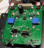
An update on my prototype like Post 157 but with two slices in parallel. It has voltage feedback and an 84V floating supply for 100W into 8 ohms.

 A 3rd slice can be added if required for more power or to drive 4 ohm loads.
Notice the bias/splitter transistors are on on the bottom under the Schottky diodes (see top view). This provides tight thermal coupling and fast thermal response. Vias are used to aid heat transfer from the Schottky's. Since my earlier posts I have discovered the amount of thermal feedback can be adjusted electrically by changing the resistors between the Schottky's and the bias/splitter transistors - this will be checked and finalised to suit this PCB.
The heatsink is a bit non-standard where the parallel NPN power transistors are on a common 'L' bracket with no thermal washers, but have a mylar sheets between the heatsink and the 'L' brackets for electrical isolation. This should improve overload capability since there is no thermal washer to deteriorate and there is more thermal mass before reaching the thermal washer. So the disadvantage of more complicated mounting has its pros and cons.
Another finding since my earlier bench tests is adding 50 milliohms to each Schottky diode reduces the optimum idle current (and mentioned in the post above). So my next PCB will have pads for adding these SMD series resistors. These resistors are also helpful for reducing the optimum idle current with MOSFETs.
Yet another finding since my earlier bench tests is adding a 33 ohm resistor across the two Schottky's (mentioned in the post above) which gives "keep-on" current for nonswitching even when starting clipping. These changes are shown in my updated circuit below (only one slice shown):

Lastly, BAT54 diodes are also added to stop the bias/spreaders from going into hard saturation during clipping, giving good recovery from clipping (at least in a simulation) with the added 'keep-on' current with added R28. Updated sim files are attached.
---------------
Repeating earlier notes on the floating power supply. The speaker is linked to the rails by two 4700uF/80V caps which provides inherent DC speaker protection which simplifies the overall amp. The single floating rail has a single 4700uF/80V capacitor which provides more efficient smoothing than the two capacitors for the speaker. This is because the two capacitors for the speaker must be rated for twice the normal DC operating voltage -- in case the output goes continuously to the rails during a fault (or the input capacitor is not used and DC is inadvertently applied).
This floating supply only needs one secondary, so twin secondary transformers can power two channels from one standard transformer, but don't forget it needs twice the voltage per winding.
--------------
Sorry it has been so long to get to this stage. I think the 3 discoveries during this time have been worth the wait. Also I have looked at several other variations and the CFP variant (above) looks very promising but needs a bench test before starting another PCB version.
Cheers, IanH
Notice the bias/splitter transistors are on on the bottom under the Schottky diodes (see top view). This provides tight thermal coupling and fast thermal response. Vias are used to aid heat transfer from the Schottky's. Since my earlier posts I have discovered the amount of thermal feedback can be adjusted electrically by changing the resistors between the Schottky's and the bias/splitter transistors - this will be checked and finalised to suit this PCB.
The heatsink is a bit non-standard where the parallel NPN power transistors are on a common 'L' bracket with no thermal washers, but have a mylar sheets between the heatsink and the 'L' brackets for electrical isolation. This should improve overload capability since there is no thermal washer to deteriorate and there is more thermal mass before reaching the thermal washer. So the disadvantage of more complicated mounting has its pros and cons.
Another finding since my earlier bench tests is adding 50 milliohms to each Schottky diode reduces the optimum idle current (and mentioned in the post above). So my next PCB will have pads for adding these SMD series resistors. These resistors are also helpful for reducing the optimum idle current with MOSFETs.
Yet another finding since my earlier bench tests is adding a 33 ohm resistor across the two Schottky's (mentioned in the post above) which gives "keep-on" current for nonswitching even when starting clipping. These changes are shown in my updated circuit below (only one slice shown):
Lastly, BAT54 diodes are also added to stop the bias/spreaders from going into hard saturation during clipping, giving good recovery from clipping (at least in a simulation) with the added 'keep-on' current with added R28. Updated sim files are attached.
---------------
Repeating earlier notes on the floating power supply. The speaker is linked to the rails by two 4700uF/80V caps which provides inherent DC speaker protection which simplifies the overall amp. The single floating rail has a single 4700uF/80V capacitor which provides more efficient smoothing than the two capacitors for the speaker. This is because the two capacitors for the speaker must be rated for twice the normal DC operating voltage -- in case the output goes continuously to the rails during a fault (or the input capacitor is not used and DC is inadvertently applied).
This floating supply only needs one secondary, so twin secondary transformers can power two channels from one standard transformer, but don't forget it needs twice the voltage per winding.
--------------
Sorry it has been so long to get to this stage. I think the 3 discoveries during this time have been worth the wait. Also I have looked at several other variations and the CFP variant (above) looks very promising but needs a bench test before starting another PCB version.
Cheers, IanH
Attachments
An update to Post 202 Autobias CFP now with FDC6321C in the CMOS input stage. I have used the FDC6320C as an alternative to the 74HCU04 CMOS array in bench tests but the the FDC6320C is now EOL and is replaced by the FDC6321C which is about 6 times the area of the FDC6320C.

BTW I have not found anything similar to the FDC6320C which has the unusual property of fairly well matched complements in one package. The lack of fairly well matched complements in one package is possibly due to the lack of demand since they are mainly used for switching applications. Analog applications, such as I am using them as a CMOS input stage is almost unknown, but has some nice properties such as differential input and soft clipping and thermal overload limiting.
Compared to Post 202 with a 74HCU04 CMOS array the FDC6321C gives a higher gain. The open loop gain is now 70dB (was 50dB) giving lower distortion (0.003% @1W) and higher DF of 100 (was 10). The input stage is operated at 11mA (was 3mA) and the output stage has 50mR diode series resistors (was 75mR) giving an output stage gain of 7A/V (was 5A/V) with a higher optimum idle current of 300mA (was 230mA). It is still a fairly simple amp although not low feedback -- but some like it like that.
BTW the higher open-loop gain means the idle current can be reduced back to about 200mA and the increased THD is still low enough to be not noticed.
(A benefit of the CFP configuration over my earlier non-CFP version, eg Post 203 version, is the peak current for a single pair of output transistors can be twice as much intermittently as the non-CFP version allowing less parallel stages for driving difficult loads with low impedance dips without incurring the higher total idle current of the extra parallel stages - I hope that makes some sense).

In Post 202 the clip level is trimmed by R24 at the + output of the CMOS input stage but this position is incorrect and needs to be at the - output which is now in series with R12 of the latest version. This resistance is usually less than 1k and can increase to 10K to reduce the clip level to a few output volts or a few output watts. You can trim this resistor to stop the power stage from going into hard clip which stops the typical slow recovery from hard clip and improves the amps clarity when over-driven. Also this resistor can be part of a thermal feedback loop to prevent the power transistors from exceeding their thermal limit when things get bad. I have tested another amp using this type of input stage and thermal feedback protection using a TLP222G photo-MOSFET as a variable resistance device with low distortion (see below). A LDR and LED is another option but I haven't tried it yet. A simpler method is a thermostat switch with a 10k shunt resistor.

An external clip power level pot can also be included to protect loudspeakers that are underrated for the power amps full rating. The external clip power level pot is great for guitar amps when practicing to keep neighbours and family on side. The full paper on this is available here: https://www.dropbox.com/scl/fi/yhui...2017.pdf?rlkey=la2hg4co2io8285vowmlmr6na&dl=0
Lastly, the circuit has Q9,Q10 added for current sources so the bias current is fairly independent of rail voltage variations. Full-power bandwidth is 300kHz and 50V/us slew rate.
BTW I have not found anything similar to the FDC6320C which has the unusual property of fairly well matched complements in one package. The lack of fairly well matched complements in one package is possibly due to the lack of demand since they are mainly used for switching applications. Analog applications, such as I am using them as a CMOS input stage is almost unknown, but has some nice properties such as differential input and soft clipping and thermal overload limiting.
Compared to Post 202 with a 74HCU04 CMOS array the FDC6321C gives a higher gain. The open loop gain is now 70dB (was 50dB) giving lower distortion (0.003% @1W) and higher DF of 100 (was 10). The input stage is operated at 11mA (was 3mA) and the output stage has 50mR diode series resistors (was 75mR) giving an output stage gain of 7A/V (was 5A/V) with a higher optimum idle current of 300mA (was 230mA). It is still a fairly simple amp although not low feedback -- but some like it like that
.BTW the higher open-loop gain means the idle current can be reduced back to about 200mA and the increased THD is still low enough to be not noticed.
(A benefit of the CFP configuration over my earlier non-CFP version, eg Post 203 version, is the peak current for a single pair of output transistors can be twice as much intermittently as the non-CFP version allowing less parallel stages for driving difficult loads with low impedance dips without incurring the higher total idle current of the extra parallel stages - I hope that makes some sense).
In Post 202 the clip level is trimmed by R24 at the + output of the CMOS input stage but this position is incorrect and needs to be at the - output which is now in series with R12 of the latest version. This resistance is usually less than 1k and can increase to 10K to reduce the clip level to a few output volts or a few output watts. You can trim this resistor to stop the power stage from going into hard clip which stops the typical slow recovery from hard clip and improves the amps clarity when over-driven. Also this resistor can be part of a thermal feedback loop to prevent the power transistors from exceeding their thermal limit when things get bad. I have tested another amp using this type of input stage and thermal feedback protection using a TLP222G photo-MOSFET as a variable resistance device with low distortion (see below). A LDR and LED is another option but I haven't tried it yet. A simpler method is a thermostat switch with a 10k shunt resistor.
An external clip power level pot can also be included to protect loudspeakers that are underrated for the power amps full rating. The external clip power level pot is great for guitar amps when practicing to keep neighbours and family on side. The full paper on this is available here: https://www.dropbox.com/scl/fi/yhui...2017.pdf?rlkey=la2hg4co2io8285vowmlmr6na&dl=0
Lastly, the circuit has Q9,Q10 added for current sources so the bias current is fairly independent of rail voltage variations. Full-power bandwidth is 300kHz and 50V/us slew rate.
Attachments
Another way not using the CFP? The CFP requires high voltage driver transistors with rail-rail Vce like the power transistors and there's the driver's SOA consideration. Then CFP's need faster drivers than the power transistors for stability requiring very fast drivers for modern fast power transistors - like 100MHz drivers for 30MHz power transistors. There are not very many suitable CFP drivers for modern fast power transistors. Skimping on driver speed or using too high value base-emitter speed-up resistors leads to the well know CFP stability problem. I would like to avoid these driver issues. My version in Post 203 avoids high voltage drivers. Below is an alternative way to drive the output stage with low voltage MOSFETs.

Here the power transistors are driven from MOSFETs with up to 80mA. It works quite well with the FDC6321C P+N array which is a 1 ohm device with sufficient gain when operated at about 55mA each array. The dissipation in each array is only 100mW since they only have about 2V across them.
The auxiliary +/-12V supply needs to supply about 200mA (5W total) but this is not a problem and since it's common is grounded only one auxiliary supply can supply several channels.
Interestingly, the input capacitance is about 300pF from the MOSFETs. With a 10k source impedance the BW is still over 20kHz and a usual size input capacitor can be used. (My previous design Post 203 with BJT drivers needs a source suitable for driving into 1k ohms and needs a 22uF input capacitor.)
One advantage over Post 203 version is the inbuilt soft-clip shown below with scalable clip level (ThermalSOA - see above Post 204 for this):

This version is low feedback - the output resistance is about 8 ohms. So there is only about 6dB of voltage negative feedback -actually, that's very low feedback! And the (simulated) distortion at 1W is still low enough IMO at 0.03%. Where soft clip starts at 45W it is 0.3% and mainly low order 3rd harmonic with the good phase relation. Looks like a candidate to bench test.
Cheers, IanH
Here the power transistors are driven from MOSFETs with up to 80mA. It works quite well with the FDC6321C P+N array which is a 1 ohm device with sufficient gain when operated at about 55mA each array. The dissipation in each array is only 100mW since they only have about 2V across them.
The auxiliary +/-12V supply needs to supply about 200mA (5W total) but this is not a problem and since it's common is grounded only one auxiliary supply can supply several channels.
Interestingly, the input capacitance is about 300pF from the MOSFETs. With a 10k source impedance the BW is still over 20kHz and a usual size input capacitor can be used. (My previous design Post 203 with BJT drivers needs a source suitable for driving into 1k ohms and needs a 22uF input capacitor.)
One advantage over Post 203 version is the inbuilt soft-clip shown below with scalable clip level (ThermalSOA - see above Post 204 for this):
This version is low feedback - the output resistance is about 8 ohms. So there is only about 6dB of voltage negative feedback -actually, that's very low feedback! And the (simulated) distortion at 1W is still low enough IMO at 0.03%. Where soft clip starts at 45W it is 0.3% and mainly low order 3rd harmonic with the good phase relation. Looks like a candidate to bench test.
Cheers, IanH
Attachments
Hi spbnevermind,
Yes. But at a snail's pace lately. Thanks for your interest. Maybe interest will get me going a bit faster. BTW I noticed one thread started 2013 and took to 2023, here https://www.diyaudio.com/community/...mance-class-ab-power-amp-200w8r-400w4r.235194, a good one too.
This thread is a hobby thing - I don't need to develop it for income and don't need it for myself. It's more to show anyone interested that there are other ways to do it.
Are you interested in a build of my design(s)?
I was on the way to making the PCB's available (probably in the vendors area). I paid an amp designer/builder to do the PCB's and SMD assembly. I hope to do a second MKII PCB version like Post 205 with a CMOS input stage. The MOSFET's have been ordered but delivery has been delayed for the initial prototype test and listening test. The MkI version as Post 203 - the same circuit was previously bench tested and listened to (see Post 157). The MKI needs a PCB revision for my latest developments (see Post 203).
Yes. But at a snail's pace lately. Thanks for your interest. Maybe interest will get me going a bit faster
. BTW I noticed one thread started 2013 and took to 2023, here https://www.diyaudio.com/community/...mance-class-ab-power-amp-200w8r-400w4r.235194, a good one too.This thread is a hobby thing - I don't need to develop it for income and don't need it for myself. It's more to show anyone interested that there are other ways to do it.
Are you interested in a build of my design(s)?
I was on the way to making the PCB's available (probably in the vendors area). I paid an amp designer/builder to do the PCB's and SMD assembly. I hope to do a second MKII PCB version like Post 205 with a CMOS input stage. The MOSFET's have been ordered but delivery has been delayed for the initial prototype test and listening test. The MkI version as Post 203 - the same circuit was previously bench tested and listened to (see Post 157). The MKI needs a PCB revision for my latest developments (see Post 203).
Yes. And I can try to design a PCB, too, but with thru-hole components wherever it possible.Are you interested in a build of my design(s)?
Hi spbnevermind,
All my PCB designs have been thru-hole but as I mentioned this autobias one was done by someone else who had all the SMD equipment and CAD so we used SMD. If/when we make PCB's available then we would provide the boards with all the SMD's for those who don't want to do SMD's.
BTW My last PCB before this autobias one allowed either SMD and/or thru-hole parts (unless the resistors were higher wattage). See below.

If you look carefully you can see a thru-hole DIP14 with SO-14 pads and also SOT-6 pads - all for the same IC but with a choice of 3 different packages. The small thru-hole resistors have holes and pads that allow 1206 resistors - they are a custom footprint that I made for this. Likewise the small transistors. I hadn't heard of anyone else that has done this. I used DIPtrace free. And the one PCB did either the LA Vol.8 MOSFET amp (updated) or the LA Vol.13 BJT amp. The info for these are on my website here.
Just offering ideas if you wanted to use them. I'm not intending to make a special thru-hole PCB version of my latest autobias amps - probably just offer PCB's with presoldered SMD's - the parts don't add much cost - postage is usually the dominant cost (to a distant region) these days. Would that be of any use for you?
All my PCB designs have been thru-hole but as I mentioned this autobias one was done by someone else who had all the SMD equipment and CAD so we used SMD. If/when we make PCB's available then we would provide the boards with all the SMD's for those who don't want to do SMD's.
BTW My last PCB before this autobias one allowed either SMD and/or thru-hole parts (unless the resistors were higher wattage). See below.
If you look carefully you can see a thru-hole DIP14 with SO-14 pads and also SOT-6 pads - all for the same IC but with a choice of 3 different packages. The small thru-hole resistors have holes and pads that allow 1206 resistors - they are a custom footprint that I made for this. Likewise the small transistors. I hadn't heard of anyone else that has done this. I used DIPtrace free. And the one PCB did either the LA Vol.8 MOSFET amp (updated) or the LA Vol.13 BJT amp. The info for these are on my website here.
Just offering ideas if you wanted to use them. I'm not intending to make a special thru-hole PCB version of my latest autobias amps - probably just offer PCB's with presoldered SMD's - the parts don't add much cost - postage is usually the dominant cost (to a distant region) these days. Would that be of any use for you?
Here's a variant of my ealier MkI version like Post 150 using Schottky diodes and the BJT driver

where I replace the Schottky diodes with silicon diodes. This allows direct connection to the auto bias spreader -- no need for the constant current sources and the base resistors. And notice no bias trimpot -- instead the number and type of diodes are varied (eg break links) for course adjustment along with the value of the series resistors, eg in the 1R to 0.47R range.
Eight pair of 1N4002 type diodes are used here with 1 Ohm resistors each of say 0.2W. This number of diodes can spread the extra heat generatated by the diodes over wider area of the PCB. Silicon diodes generate twice the heat of the previous version with Schottky diodes.
With Schottky diodes the heat was about 1W total and 300mW in the two diodes series resistors (50mR each) when driven to near clip and for one slice (for a 50W slice). With silicon diodes this doubles to 2W over the 16 diodes (125mW each) and 700mW over the 16 resistors (45mW each). I expect my PCB's can handle this extra heat.
Simm'ed linearity is about the same with 0.06% THD at 1W with 230mA idle current and fast rolloff of higher harmonics (mainly 3rd).


The Schottky version was 0.04% with 190mA bias.
So it looks to me like a viable option. The extra D+R part count is not a big issue for me. It's mainly trading some extra diode heat for bias simplicity and bias robustness. Bench tests will show if the bias trimpot can be omitted as assumed. It should sound great!
where I replace the Schottky diodes with silicon diodes. This allows direct connection to the auto bias spreader -- no need for the constant current sources and the base resistors. And notice no bias trimpot -- instead the number and type of diodes are varied (eg break links) for course adjustment along with the value of the series resistors, eg in the 1R to 0.47R range.
Eight pair of 1N4002 type diodes are used here with 1 Ohm resistors each of say 0.2W. This number of diodes can spread the extra heat generatated by the diodes over wider area of the PCB. Silicon diodes generate twice the heat of the previous version with Schottky diodes.
With Schottky diodes the heat was about 1W total and 300mW in the two diodes series resistors (50mR each) when driven to near clip and for one slice (for a 50W slice). With silicon diodes this doubles to 2W over the 16 diodes (125mW each) and 700mW over the 16 resistors (45mW each). I expect my PCB's can handle this extra heat.
Simm'ed linearity is about the same with 0.06% THD at 1W with 230mA idle current and fast rolloff of higher harmonics (mainly 3rd).
The Schottky version was 0.04% with 190mA bias.
So it looks to me like a viable option. The extra D+R part count is not a big issue for me. It's mainly trading some extra diode heat for bias simplicity and bias robustness. Bench tests will show if the bias trimpot can be omitted as assumed. It should sound great!
Attachments
Thanks for the thumbs up guys!
I was looking through my parts bins for diodes and found I have enough 1N4007's. So I simulated my amp with them to see any difference to IN4002's.

To switch between models I use the .model ako method, where the diode model is assigned a number (text won't work here),
Now all 16 diodes can be changed with this statement. The 'IS' (saturation current) value is changed to suit my 1N4007's. I use 10n instead of 14n (the value in the Bordodynov library). 10n gives the same forward voltage as I measured with my DMM. I use a jig on my circuit (not shown above) to generate the forward voltage of the diode at my room temperature (see my attached file for the jig). I also measured the Vbe of the bias transistors on my PCB with my DMM and trimmed the IS value for their models (NPN IS=3e-14 and PNP IS=9e-14).
Another change are the series emitter resistors so they can be trimmed without changing all 16 diode sereis resistors. Rd for the diodes is 0.22 Ohm is about 5 times the diode model RS value which may be sufficient to stabilize current sharing while allowing enough adjust range for the Rs resistors. Trimming Rs allows the THD in the 1W output region to be minimised, but it is not expected to be a critical adjustment (bench tests needed to confirm).
Notice the number of diodes used here is 7 of the 8 pairs for 220mA idle current. With 8 pairs it's 250mA. So adding more pairs increases the width of the linear region (the width also depends on how many parallel stages are used and the nominal load resistance). And 7 of the 8 pairs seems about right for a single slice amp (50W, 8 Ohms) with 1N4007's or similar.
I was looking through my parts bins for diodes and found I have enough 1N4007's. So I simulated my amp with them to see any difference to IN4002's.
To switch between models I use the .model ako method, where the diode model is assigned a number (text won't work here),
Code:
.model 1 ako:1N4007 IS=10nAnother change are the series emitter resistors so they can be trimmed without changing all 16 diode sereis resistors. Rd for the diodes is 0.22 Ohm is about 5 times the diode model RS value which may be sufficient to stabilize current sharing while allowing enough adjust range for the Rs resistors. Trimming Rs allows the THD in the 1W output region to be minimised, but it is not expected to be a critical adjustment (bench tests needed to confirm).
Notice the number of diodes used here is 7 of the 8 pairs for 220mA idle current. With 8 pairs it's 250mA. So adding more pairs increases the width of the linear region (the width also depends on how many parallel stages are used and the nominal load resistance). And 7 of the 8 pairs seems about right for a single slice amp (50W, 8 Ohms) with 1N4007's or similar.
I powered up the previous circuit using +/-23V rails with 7 pairs of 1N4007 diodes. I didn't have 14x0.22 Ohm resistors so I used 0.51 Ohm 1/4 watters.


I disconnected the Schottky diodes and wired the D+R array direct to the autobias bases (as shown in Post 211 above). The diodes had builder filler for a thermal connection to the PCB (which has the autobias transistors on the reverse side to the Schottky diodes) for thermal compensation as the diodes heat up. Also a 56 ohm 'keep-on' resistor (not shown) was used between the autobias transistor bases giving about 10mA extra idle current.
Despite the diodes offset to the bias generator it works OK thermal wise. The idle current at turn on was 150mA and operating at 18W with a sinewave for 10 minutes and the idle current on removal of the sinewave was 160mA. When run harder with some clipping at about 50W for 10 minutes the idle current increased to about 240mA and fell quickly (10 seconds) to about 200mA then returning to 150mA once cooled. So the thermal loop is acceptable (no thermal runaway) but not optimal if overdriven for long periods with bench tests. But for music, where clipping is avoided it would be fine. Maybe with the diodes mounted on the PCB AND directly over the autobias transistors, then the the bias will be more constant with had clipping? (Test needed).
The diodes and resistors got hot to touch (about 50C or 30C rise) with hard clip. But not too hot - as I had hoped in Post 210. And with 0.22 Ohm diode resistors the heat will be less than in this test. Or even 0.1? Ohm diode resistors if two sets of 7 diodes are matched using a DMM (eg +/-5mV).
I think the accuracy of idle current when going from my simulation to my build is OK (230mA in simulation and 150mA build). That's with a DMM reading my diode voltage and transistor Vbe's and adjusting the models to get the same voltages at my room temperature (as mentioned above). The difference between measured and simulated appears to be diodes voltages in the build had a slightly different average voltage than the simulation which used a single diode voltage.
Without a trimpot for bias trimming it should be possible to selet jumpers for say 6 to 10 diodes per side to allow for different manufacturers 1N4004's and different batches. It would be nice to dispense with the bias trimpot. The ideal target idle current is about 230mA according to the simulations -- but listening tests are needed to confirm whether anything in the range of 150mA to 230mA would be acceptable sound-wise.
So far it looks OK 1) thermal-wise and 2) repeatability-wise without the bias trimpot when using arrays of 1A diodes.
Last edited:
More tests. XY plot with 4 ohms, 5 amps peak giving 50W, 54V supply. Linear region about +/-4V into 4 Ohms, first 2W. Idle current is 240mA at instant of removal of power reducing to 150mA long term.

I also measured the diode temperature rise with 2W output. It was 20 deg C rise (versus 70C rise at full power). That means music use will not overheat the PCB.
Linearity is as good as previous prototype (Post 154) so with music (averaging around 1W) theres no audible distortion (at least to my ears).
Last edited:
Yet another option using MJE3055/MJE2955 as diodes. They are TO-220, less cost and smaller packages than say MJL3281/1302.

With bases shorted to collector to make BJT diodes the idle current is too high -- about 600mA at turn on and rising to about 800mA at full power. Adding base to collector resistors of 0.5 ohms the BJT diodes voltage can be varied slightly with a base-to-base resistor. With the values shown my bench test gave 200mA at turn on, rising to 300mA warmed up. Full power idle current rises to 600mA and falls back to 300mA. Linearity is quite good for the first few watts. Running at 2W the idle current stays at about 300mA - so idle current is quite stable with typical music levels (once warmed up).

 XY plot is 5A peak at point of clip. Input voltage (X-axis) is 0.8V. Voltage gain is 19dB into 4 Ohms. Much the same as previous with 7 pair of 1N4004 diodes.
The MJE3055/MJE2955 were mounted where the Schottky diodes were. The MJE3055 (NPN) had a thermal washer - another PCB would allow both to be soldered to the PCB (for better thermal linking to the auto-bias spreaders under the PCB).
Several problems were encountered. First, base stopper resistors were needed to stop a step/glitch occuring with a sinewave crossing around the idle current. Also, resistor R8 (Rb) was reduced to increase the "keep-on" current in the power transistors to fully remove the step/glitch which had to be 56 Ohms.
Second, the PNP diode was not quite the same as the NPN diode causing some asymmetry, mainly at lower power. If both diodes were made with NPN's the this assymmetry is eliminated, but then the bias cannot be so easily trimmed (maybe trim each Rbc separately?)
So it's doable with BJT diodes. But I think I prefer the 7 pair of 1N4004's for better setting of idle current range (eg using links) and better stability -- despite a higher part count.
BTW, thanks for your likes.
With bases shorted to collector to make BJT diodes the idle current is too high -- about 600mA at turn on and rising to about 800mA at full power. Adding base to collector resistors of 0.5 ohms the BJT diodes voltage can be varied slightly with a base-to-base resistor. With the values shown my bench test gave 200mA at turn on, rising to 300mA warmed up. Full power idle current rises to 600mA and falls back to 300mA. Linearity is quite good for the first few watts. Running at 2W the idle current stays at about 300mA - so idle current is quite stable with typical music levels (once warmed up).
The MJE3055/MJE2955 were mounted where the Schottky diodes were. The MJE3055 (NPN) had a thermal washer - another PCB would allow both to be soldered to the PCB (for better thermal linking to the auto-bias spreaders under the PCB).
Several problems were encountered. First, base stopper resistors were needed to stop a step/glitch occuring with a sinewave crossing around the idle current. Also, resistor R8 (Rb) was reduced to increase the "keep-on" current in the power transistors to fully remove the step/glitch which had to be 56 Ohms.
Second, the PNP diode was not quite the same as the NPN diode causing some asymmetry, mainly at lower power. If both diodes were made with NPN's the this assymmetry is eliminated, but then the bias cannot be so easily trimmed (maybe trim each Rbc separately?)
So it's doable with BJT diodes. But I think I prefer the 7 pair of 1N4004's for better setting of idle current range (eg using links) and better stability -- despite a higher part count.
BTW, thanks for your likes.
Attachments
Now the question of using 3A diodes. Can a pair of 3A diodes be used without a trimpot? Here's some test results.


First 1N5408's. Idle current warmed is 160mA, full power drops from 250mA in a few seconds then slowly to 160mA. With 2W, idle current stays at 160mA.


Second: 1N5404's. Idle current warmed is 170mA, full power drops from 260mA in a few seconds then slowly to 170mA. With 2W idle current stays at 170mA.
Both cases are into 4 ohms, 5A peak at start of clip. Both 56 Ohm keep-on resistor and 10 ohm base stoppers.
The second one appears to be slightly more linear over the first watt region.
Strangely, the two different versions of the 3A diodes had quite different voltages on my DMM: IN4008's were 492mV and 501mV at 17C, while the 1N4004's were 426mV and 426mV. That large difference was not reflected in the measured idle currents above. I have to conclude that testing the diode voltages at the DMM'd 300uA does not give a useful indication of what the idle current will be. So these diodes need to be tested closer to the actual operating current to be useful here. This disparity may be due to differences in the model parameter 'N' (ideality factor), which appears to vary between manufacturers and voltage ratings.
These tests show 3A diodes can be used instead of many 1A diodes in parallel and the idle current is in about the right range for this amp. And two quite different pair of diodes and different manufacturers gave about the same idle current and linearity. SMD 3A diodes should give better thermal compensation. But compared to the previous 7 pair of 1A diodes the linearity seems to be slightly better in the first few watt range with the 7 pairs. It's possible that it's due to the additional 7x0.51 Ohm series resistors? YTBD. Sims show a small series resistor helps the lower power region linearity.
First 1N5408's. Idle current warmed is 160mA, full power drops from 250mA in a few seconds then slowly to 160mA. With 2W, idle current stays at 160mA.
Second: 1N5404's. Idle current warmed is 170mA, full power drops from 260mA in a few seconds then slowly to 170mA. With 2W idle current stays at 170mA.
Both cases are into 4 ohms, 5A peak at start of clip. Both 56 Ohm keep-on resistor and 10 ohm base stoppers.
The second one appears to be slightly more linear over the first watt region.
Strangely, the two different versions of the 3A diodes had quite different voltages on my DMM: IN4008's were 492mV and 501mV at 17C, while the 1N4004's were 426mV and 426mV. That large difference was not reflected in the measured idle currents above. I have to conclude that testing the diode voltages at the DMM'd 300uA does not give a useful indication of what the idle current will be. So these diodes need to be tested closer to the actual operating current to be useful here. This disparity may be due to differences in the model parameter 'N' (ideality factor), which appears to vary between manufacturers and voltage ratings.
These tests show 3A diodes can be used instead of many 1A diodes in parallel and the idle current is in about the right range for this amp. And two quite different pair of diodes and different manufacturers gave about the same idle current and linearity. SMD 3A diodes should give better thermal compensation. But compared to the previous 7 pair of 1A diodes the linearity seems to be slightly better in the first few watt range with the 7 pairs. It's possible that it's due to the additional 7x0.51 Ohm series resistors? YTBD. Sims show a small series resistor helps the lower power region linearity.
Attachments
Today I was going to use 8 pair of SMD IN4004's without resistors. So far I have soldered 4 pair and did a test:


The idle current is down as expected at 130mA with a 56 ohm resistor across the diodes, but no resistors in series with the diodes. Linearity is not that good.
As a reality check I re-did the XY plot for the earlier 7 pair 1N4007's each with a 0.51 Ohm series resistor. See Post 213. Below shows linearity is definitely better before with the extra diodes and R's.

Idle current is 150mA but it goes to 240mA when doing this XY test. The 4 pair 1N4004.s only go to 180mA with the XY test (its less increase due to tighter thermal linkage with SMD's to the spreader transistors underneath).
It looks like 8 diodes (or more?) are needed with some series resistance to get as good linearity as this. I don't have any 0.22 Ohm SMD series resistors on hand so I'll have to try 50m Ohm in series. Notice seven 0.51 Ohms in parallel is equivalent to 75mR diode series resistance.
The idle current is down as expected at 130mA with a 56 ohm resistor across the diodes, but no resistors in series with the diodes. Linearity is not that good.
As a reality check I re-did the XY plot for the earlier 7 pair 1N4007's each with a 0.51 Ohm series resistor. See Post 213. Below shows linearity is definitely better before with the extra diodes and R's.
Idle current is 150mA but it goes to 240mA when doing this XY test. The 4 pair 1N4004.s only go to 180mA with the XY test (its less increase due to tighter thermal linkage with SMD's to the spreader transistors underneath).
It looks like 8 diodes (or more?) are needed with some series resistance to get as good linearity as this. I don't have any 0.22 Ohm SMD series resistors on hand so I'll have to try 50m Ohm in series. Notice seven 0.51 Ohms in parallel is equivalent to 75mR diode series resistance.
Attachments
Now with 8 pair SMD 1N4004's and no series resistors for each diode nor for each pair. Idle current now 190mA and goes to 260mA in full power XY test into 4 Ohms and falls back to 190mA in abut 10 seconds.


The first amp region (first 2 watts) is now more linear and wider. But it's still not as linear as the earlier 7x1N4007's each with 0.51 Ohm resistors. So it must be these resistors improve linearity. Unfortunately I can't add them to my PCB to test this - I'll have to wait for the next PCB version. For now I'll assume they are beneficial.
When run at 2W for a while the idle current rises only slightly to 200mA then quickly falls back to 190mA - nice. When run at 2W for a while the diodes heat up to 40C (23C rise) while the heatsink reaches 50C (33C rise). So with 8x1A SMD diodes in parallel on my smallish PCB they are not running too hot for typical music use - nice. BTW I selected the diodes using my DMM to +/-10mV because I didn't have any 0.22 Ohm series resistors for them. Yet they seemed stable without the resistors, but I'll include them on my next PCB version( and they can be used as links to select how many diodes are used in parallel, maybe up to 10 per side).
Now tests with two slices in parallel like Post 138 but here with 105V rail (+/-52.5V). I used the 8x1N4004 PCB plugged on top of the 7x1N4007 PCB and ran wires from the top PCB to the second heatsink.


The idle current is now 420mA at idle (starts at 380mA) and run at just clip full power (150W into 8 ohms) the idle current at removal was 520mA falling to 470mA after a few seconds then slowly back to 480mA. The linearity looks very good up to about 10W. Very pleasing -- except for the 50W of idle dissipation.
To run 4 ohms with these 2 slices the supply rails would need to be lowered. I used a dual 30V 300VA transformer so for 4 ohms a 50V secondary would be better. Alternatively, for 4 ohms use 3 slices with a 60V secondary and a 500VA transformer giving 300W.
To summarise developments so far: This autobias amplifier does not need a bias trimpot. It can uses either BJT's or MOSFET power transistors - even mix and match slices, one with BJT's and another MOSFET's. The output impedance is high due to almost no feedback - about 6dB of feedback giving about 8 ohms. For Magneplanar's this is not a problem but are 4 ohms. For custom 8 ohm speakers it's not a problem. You can use a Sokol parameteric equaliser, see 'Practical Subwoofer Design', Wireless World Dec 1983 and improved version May 1996.
Last edited:
- Home
- Amplifiers
- Solid State
- Towards a wideband non switching Auto Bias power amp