Hi All,
For some time I've wanted to play with TP60 so I ordered one a while ago. Always wanted to bypass the volume control and have it as a stand alone amp cause I'm too lazy to get off the couch to turn the volume up and down.
Anyways, ordered the Tortuga LDR3x for remote control volume control and thought I'd give the old LDR a try.
Took out the TP60 Pot using soldering iron and solder sucker. Took out the relay and jumpered the pins on the relay and pot. Signal now goes straight to input caps.
The setup works! I'll save the impressions for later but if anyone wants to know if this setup is compatible, it is! Wow, first time I've run a low power amp on my pro woofer, compression drive home brews with reasonable gain stages on equipment. A few watts goes a long long way .
.
Side note, not sure how well the tracking between channels on the ALPS are suppose to be, but mine were out quit a bit.
Cheers
For some time I've wanted to play with TP60 so I ordered one a while ago. Always wanted to bypass the volume control and have it as a stand alone amp cause I'm too lazy to get off the couch to turn the volume up and down.
Anyways, ordered the Tortuga LDR3x for remote control volume control and thought I'd give the old LDR a try.
Took out the TP60 Pot using soldering iron and solder sucker. Took out the relay and jumpered the pins on the relay and pot. Signal now goes straight to input caps.
The setup works! I'll save the impressions for later but if anyone wants to know if this setup is compatible, it is! Wow, first time I've run a low power amp on my pro woofer, compression drive home brews with reasonable gain stages on equipment. A few watts goes a long long way
.Side note, not sure how well the tracking between channels on the ALPS are suppose to be, but mine were out quit a bit.
Cheers
Hello mike,
I intend to do the exact same thing (bypassing the volume pot), but when I read your post, you got me thinking about what you said about the relay. I can't figure out where it comes into play in this case. Can you please enlighten me?
Did you finish your mod? How does it sound?
Thanks!
I intend to do the exact same thing (bypassing the volume pot), but when I read your post, you got me thinking about what you said about the relay. I can't figure out where it comes into play in this case. Can you please enlighten me?
Did you finish your mod? How does it sound?
Thanks!
Hi All,
My topping TP60 has 2 inputs, so the board has a relay that selects which input is plumbed into the amplifier. I don't believe the TP20 has 2 inputs, only the one so you probably don't have to bypass the relay in that one.
The TP60 takes both inputs from the back RCA jacks and both pairs go to a relay. The relay looks to be reasonable quality though. From the relay it goes to the front panel POT. Nothing wrong with the pot and the pot seems reasonably quite but when I measured the resistance dividers, they were out a bit so channel balance was out slightly.
After the pot, the signals go through the required DC blocking caps (the cap is required by the tripath chip to function properly).
I left the stock caps in but was toying with the idea of trying different ones. I'm away from home right now but can put pics of the board mods up later.
Cheers
Regarding the sound. I liked the TP60 presentation before the mods but I found my entire system went up a notch when a few things were fixed.
1. The gain stage between my DAC (XDA-1 fire sale) and AVR was not correct. I digitally attenuated the source(PC TOSLINK) too much before going to the DAC. I wanted to avoid clipping but went too far. I finally measured the output as the spec sheet said "1V RMS nominal". Not sure if that meant MAX or not. That said the output of the XDA-1 vs my PC sound card (Essence ST) were different. XDA-1 was slightly higher. Too high for the miniDSP 2VRMS MAX input setting. After fixing this, sound quality went up a lot.
2. Used the Tortuga board as the volume control. This forced me to mod the Topping TP60 to by-pass the onboard POT. Decided to bybass the relay too. The tortuga board has 3 input select lines so not need to use the topping as selectors. Also the remote feature is nice, now have remote control for the topping.
3. Figured out how to get ASIO from the output of the PC toslink to DAC.
I kindof did all of the above at once so there so its hard to say which was the biggest improvement. One thing to note is if you don't have a way to balance the left and right speaker amplitudes, they will possibly be out of balance when using the Topping ALPS pot.
Cheers
Last edited:
Hi All,
I don't have time to post pics today but should be able to make a short write up in the next few days. I couldn't find a reasonable 'how to' guide for the TP60
on this (although I didn't look that hard).
If there is a how-to guide around here maybe someone could link the thread? I know it is not difficult as it is mostly just the POT bypass but perhaps a step-by-step could be useful.
Cheers,
Thank you Mike.
I am receving the TP20 tomorrow (good ol Amazon Prime) and I will take a look and listen. If its any better than my Audiolab pre-power combo I might consider bypassing the POT and using it with my Audiolab Pre
Btw, would there be a sonic benifit in removing/bypassing the pot? Or would it be the same as setting the pot on 100%?
Hi dakku,
I try and stay away from subjective assessment of things like the volume control. Some people like stepped resistors, others LDRs others op-amps. From what I've read, the jury is still out on the best one.
That said, the one concrete thing I can say is the ALPS pot that came with my TP60, was it was NOT balanced. The Left and Right channels measured differently. Can't remember by how much but was more than I was comfortable with. It made me look closer at my channel amplitudes. My room probably masks some of the differences but.........since I'm not an expert on speaker imaging and the potential problems of unbalanced stereo presentation, I could not comment on the repercussions.
If you could ensure the L/R balance of your entire system is matched I would suspect there wouldn't be much difference between the POT wide open and no pot; however, some people have better ears than me and my LDR does sound a bit different than my AVR. The LDR 'seems' a hair more detailed in the ultra extremes of the frequency bands. In a double blind test I might not be able to pick a difference between different kinds of volume control. To my ears, the differences are small at best.
Agreed.
I think the main point for those who say that no pot is better, is the fact that it is just one more "standard" component in the signal path. Depending on the quality and wear of the pot it can really degrade SQ IMO.
Mike, I feel I would be able to do the pot mod, but I am still not so sure about the relay one. If you find the time to take the pictures, It would be really good.
Gg
I think the easiest would be to:
1. Take out the pot.
2. Run the positive lines of one RCA pair from the back panel directly to the large input caps. Could follow the PCB lines from the pot wiper to the caps of interest.
3. Run the GND lines of the RCA to the GND of the board. Closest GND point to the input caps would probably be best.
I'll verify the connection points on a pic later.
Mike
Hi All,
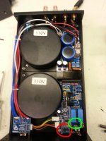
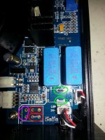
In the full view pic the Red circle was the POT, the Green circle was the Relay. I didn't want to cut the RCA cables that run from the back of the unit to just beside the circles, so I jumpered the PCB. The other picture is a zoomed in pic of the area of interest.
In that pic the green circles are 0R (0 ohm)wire jumpers for the relay. The red circles are 0R (0 ohm) wire jumpers for the pot. These simple pass the POS signal from the RCA connections to the input Caps. The input cap connections are circled in blue. If you flip over the board, you can get at these connections. The purple circles are the GND or negative signal reference. All the RCA negative/reference on the back panel are electrically connected to those points.
I've had this running for the last 3 months so seems to work with a passive pre-amp.
Cheers,
Attachments
Mike, I have not enough words to tell you how greatfull I am. You taking the time to open up your unit just to take the
pictures, plus drawing the circles and explaining everything. Man, things like that make the comunity. In the future, I hope I will be able to help other members as you've helped me. THANK YOU!
Now it is crystal clear to me what must be done, both to the pot and to the relay. But there is one thing I read in other
posts regarding pot bypass that I feel I must bring to light so you guys can say what you think. I will try to explain it
the best I can, despite the quality of my English. I hope you can understand:
When the pot is in place and let's say it is all the way up (full clockwise position) the circuit sees zero resistence on one "side" and full resistence on the other "side". So according to other members (will try to find the posts later), in order to correctly bypass the pot, one must not only jump the 0 ohm "side" with a 0 ohm wire, but must also add
a fixed resistor to the other "side" so that the circuit will "think" the pot is still there, but turned all the way up.
They say this is important, because you can have impedance problems if you just jump the signal without adding the fixed
resistor to the other "side". Needless to say, this fixed resistor's value must be the same as the pot's full resistence.
I hope I made myself clear. What do you think?
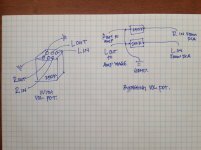
I've attached this drawing that I've copyed from the other post that I can't recall. The drawing was made by another member, not by me. Sorry I don't remember his name right now to give it the propper credit.
Gg
pictures, plus drawing the circles and explaining everything. Man, things like that make the comunity. In the future, I hope I will be able to help other members as you've helped me. THANK YOU!
Now it is crystal clear to me what must be done, both to the pot and to the relay. But there is one thing I read in other
posts regarding pot bypass that I feel I must bring to light so you guys can say what you think. I will try to explain it
the best I can, despite the quality of my English. I hope you can understand:
When the pot is in place and let's say it is all the way up (full clockwise position) the circuit sees zero resistence on one "side" and full resistence on the other "side". So according to other members (will try to find the posts later), in order to correctly bypass the pot, one must not only jump the 0 ohm "side" with a 0 ohm wire, but must also add
a fixed resistor to the other "side" so that the circuit will "think" the pot is still there, but turned all the way up.
They say this is important, because you can have impedance problems if you just jump the signal without adding the fixed
resistor to the other "side". Needless to say, this fixed resistor's value must be the same as the pot's full resistence.
I hope I made myself clear. What do you think?
I've attached this drawing that I've copyed from the other post that I can't recall. The drawing was made by another member, not by me. Sorry I don't remember his name right now to give it the propper credit.
Gg
Attachments
Last edited:
Hi ggmesquita,
Thank you for the kind words. Makes posting information worth while!
If I understand you, you are mostly correct in that most amplifiers have a pulldown resistor so the input to the amplifier doesn't float and make your speaker do bad things. Also some amplifiers input stage my be dependent on the RC filter it sees so one must be careful to not change the filter values or early roll off in the low end may be observed.
That said looks like the topping TP60 circuit topology is quite close to the tripath datasheet so in this respect, no pulldown is required for the circuit to be stable.
Mike
Last edited:
Yes, you got it right. I am talking about the pulldown resistor.
Great. I didn't realize it depended on the topology. It is good to know that the Tripath's design doesn't require a pulldown resistor. But do you think there is any benefit in adding it to the mod, since that is what the actual pot would do to the circuit?
Gg
Great. I didn't realize it depended on the topology. It is good to know that the Tripath's design doesn't require a pulldown resistor. But do you think there is any benefit in adding it to the mod, since that is what the actual pot would do to the circuit?
Gg
Hi ggmesquita,
Not sure whats going on in the drawing you've provided. Looks like there is 250k in series with the RCA lines and after the resistor the lines are hard wired to GND. Seems like the input signal would drop all voltage across the resistor and the amp would only see a GND signal but difficult to know for sure what it is feeding. This drawing seems to pertain to a very specific type of circuit topology.
In general, the pot emulates the resistor divider so the inline resistance will be small, the pull down to GND will be large. This ensures most of the voltage is seen by the amplifier input as most of the voltage is across the resistor to GND.
You could add the pulldown to resistor to the circuit and it will behave the same. Not sure what value the pot is on the TP60, either 25k or 50k I think.
Hope the above makes sense. I do not explain things well sometimes.
Mike
I see. That drawing must be specific then. When I first saw it, I thought the exact same thing, If the resistors are in series with the RCA lines, it would be the same as turning the pot all the way DOWN, not UP...
When I was researching, they also said that there must be a load on the input, so that the circuit of device where the signal is coming from (let's say a pre amp) sees the load and recognizes that both devices are properly connected. I think I'll go ahead and add the resistors just in case.
Thanks again!
- Status
- This old topic is closed. If you want to reopen this topic, contact a moderator using the "Report Post" button.
- Home
- Amplifiers
- Class D
- Topping TP60 Volume Bypassed