Bas Horneman,
I haven't a clue how the transformers are made. I do know where I (might) be able to buy some, though. I think I will build a small DAC based on the 1892 receiver for experience, rather than the DDDAC. I just don't like the idea of stacking the DAC chips like that.
Elso,
Thank you for the links and your ideas. I will read about the KWAK-DAC, and regardless of whether or not I choose to build an incarnation of it, I find that name very entertaining for some reason.")
I haven't a clue how the transformers are made. I do know where I (might) be able to buy some, though. I think I will build a small DAC based on the 1892 receiver for experience, rather than the DDDAC. I just don't like the idea of stacking the DAC chips like that.
Elso,
Thank you for the links and your ideas. I will read about the KWAK-DAC, and regardless of whether or not I choose to build an incarnation of it, I find that name very entertaining for some reason.
there is reason why i build it this way: I made a couple different DAC boards, and still more to come. I don´t need to build an own power supply and own output stage for them, but simple put another DAC board in and compare. This is prototyping, not building a final design. The purpose is experimenting with different DACs and implementations.
So far i finished 3 DAC boards, 2 power supplys and one D1 output board. Halfway i have 1 Dac board and a second output stage -- modular Dac test system.
I don´t belive regulator or PCB design narcsim is what gains much progress. When i try to make the perfect grounding scheme PCB for each DAC and topoligie to test, i will need some hundred years before i can draw conclusions. For some others it much easier: they make one perfectly looking red silkscreen blue LED expensive opamp PCB, and of course without building many prototypes before they found the best sounding DAC worldwide. I´m not kissed by this mighty audiophile design ghost and need design making my hand dirty before telling something would be the final solution.
jean-paul said:Maybe Hajime wants a top notch DAC without its own signature
Could be, but judging by his comments and questions I thought Hajime was pretty keen on matching the sonic performance of an Audio Note DAC-5.
“I find the Audio Note and Wadia DACs the most interesting”
“If I could make an Audio Note DAC5 I'd be very happy”
“If you could point me to the location of the AN DAC-5 schematic”
In the reviews of the Audio Notes DACs I have read it is agreed that the higher number DACs sound better. If you look at the AN DAC comparison, linked elsewhere in this thread, you will see that the configuration of the DAC-5 is essentially the same as the DAC-4 Balanced, except for the transformers. From that, I concluded that the silver transformers must be responsible for the unique sonic performance of the DAC-5 and if Hajime wanted to match its performance he would have to use the same transformers. It’s like cooking: Saffron is very expensive but nothing else matches its color, taste, and fragrance.
For the rest of you too lazy to go to the Audio Note web site and click on Products>Transformers, here is the link: (but be warned, you might have to scroll down a few pages to get to the technical stuff)
http://www.audionote.co.uk/kits/transformers.htm
For the rest of you too lazy to go to the Audio Note web site and click on Products>Transformers
LOL...that would be me.
PS..I did go to the site but I suppose they are better at building amps.
By the way..there is no Products>Transformers option.
Thanks for the link..otherwise I would have spent another hour looking for it.
It is under Kits and components -> Transformers
Cheers,
Bas
Hajime said:I actually may be able to get ahold of some silver transformers.
FYI: There are a number of inexpensive “silver-wire” transformers in circulation. Some even bear an Audio Note logo. If you happen to buy one and cut it open you will likely find the windings are copper and only the lead-out wires are silver.
Schematic
Hi Till,
I simply posted my email to you.
Attached is the schematic. It comprises a low noise reference LT1021, but AD586 will work as well, a low pass filter and buffer taken from the OP176 datasheet and a +5V to -5V voltage inverter taken from the REF02 datasheet. In the schematic a 1µF cap is pictured across the buffer but the 100µF as in the Analog Devices paper works better.
For the TDA1543 -5V is not used and +5V only for the PLL of the CS8412. Initially this circuit was used with the AD1864 later the AD1865N-K. The small circles at the bases of the transistors are ferrite beads. Later I switched to 510 Ohm and 100µF in the low pass filter after the reference.
Thanks go to Pedja for converting the Postscript file to GIF.
till said:Elso, as far as i remember you was one of the few posting on topic here...
I´m interested in your regulator, but i don´t know if Hajime is. You posted a zehner regulator schematic once, and posted a link in my zehner thread.
I emailed you yesterday because of the inverter thread, but as you didn´t respond i don´t know if mail reached you.
what definitely will not help is posting statements like "you can´t" in a thread like this.
Hi Till,
I simply posted my email to you.
Attached is the schematic. It comprises a low noise reference LT1021, but AD586 will work as well, a low pass filter and buffer taken from the OP176 datasheet and a +5V to -5V voltage inverter taken from the REF02 datasheet. In the schematic a 1µF cap is pictured across the buffer but the 100µF as in the Analog Devices paper works better.
For the TDA1543 -5V is not used and +5V only for the PLL of the CS8412. Initially this circuit was used with the AD1864 later the AD1865N-K. The small circles at the bases of the transistors are ferrite beads. Later I switched to 510 Ohm and 100µF in the low pass filter after the reference.
Thanks go to Pedja for converting the Postscript file to GIF.
till said:large amount of pins =! good sound
a diy triode will not need to much pins, maybe 5 ?
For the dsp: i´m glad there are DIP28 dspics out there...
It is not about the pins per se more about your tendancy to make your choices on the basis of how many pins the circuit has as opposed to whether or not it does the job. The thread about the TDA1541 in simultaneous mode springs to mind.
Ahh yes the DSP again. Good luck with the dspics but you might want to consider reading the datasheets below you start doing cartwheels and handstands. BTW Have you considered that this blind faith in dsp chips as a universal solution is a result of your refusal to put in the effort to understand the basics of what you are doing?
In software you can play different ways until it works and understand much faster than with some dozent logic chips...
When i asked for advice how to control some relais for a my volume control some yesterday-fanatics also suggested logic and counter chips et cetera. I´m absolutely sure the microcontroller solution i´ve choosen is better. (small parts- and pin count)
Again: is see 2 ways for the logic before the DAC: complex, so better everything integrated in one chip ---> will lead us to dsp usage, or as simple as possible ---> few devices, few pins. Don´t start to tell me about decoupling and grounding issues but advice to use 20TTLs or so.
I never claimed to understand much, but at least my DACs work. Many circuits posted on this board i tried and they did not work as they should.
Some people always tell they can do better, what those who still post what they build here is mess, but can´t give simple answers on simple questions. Is this a stategie to gain reputation? If i ask anything some Klugscheisser tells read the datasheet. If i built something and it works, they tell: nothing new, only datasheet ciruit...
btw: i read them. But some, especially the Philips datasheets, are a mess compared to Analog or TI datasheets.
In another forum where I spend time there is a chap that signs off his posts with line " When all you have is a hammer, every problem looks like a nail." Well Till, software would appear to be your hammer.till said:In software you can play different ways until it works and understand much faster than with some dozent logic chips...
Horses for courses. It is a case of picking the right tool for the job. A microcontroller is great for controlling relays but less than ideal for connecting the DF1704 to the TDA1541A.
When i asked for advice how to control some relais for a my volume control some yesterday-fanatics also suggested logic and counter chips et cetera. I´m absolutely sure the microcontroller solution i´ve choosen is better. (small parts- and pin count)
Utter rubbish. The circuitry is what it is and that is the circuitry required for the job.
Again: is see 2 ways for the logic before the DAC: complex, so better everything integrated in one chip ---> will lead us to dsp usage, or as simple as possible ---> few devices, few pins. Don´t start to tell me about decoupling and grounding issues but advice to use 20TTLs or so.
Despite being clueless as to what circuitry is required, you constantly state that complex logic or circuitry requiring more than one logic IC automatically calls for a DSP chip. What is required flows from what needs to be done and you use what is appropriate. If a task absolutely calls for a 32bit shift register then you use a 32 bit shift register. Using anything less is pointless and whinning about it won't make any difference.
More to the point, you don't seem to want to understand much.
I never claimed to understand much,
Most things are variations on the datasheets, its when you try to do a little more than application note cloning that things get interesting and this in return requires more effort than standing on sidelines dogmatically refusing to open your eyes to all possible options.
but at least my DACs work.
Many circuits posted on this board i tried and they did not work as they should.
Some people always tell they can do better, what those who still post what they build here is mess, but can´t give simple answers on simple questions. Is this a stategie to gain reputation? If i ask anything some Klugscheisser tells read the datasheet. If i built something and it works, they tell: nothing new, only datasheet ciruit...
A bad workman always blames the tools.
btw: i read them. But some, especially the Philips datasheets, are a mess compared to Analog or TI datasheets.
your example is missguiding, who whats to connect DF1704 to TDA1541A? I not. And a dsp would substitute all kind of filters and logic before the DAC.
What do you want to proof? Do you have a mental problem anybody ales but you gets a DAC working?
Jean - Paul, whats the problem with my tone for now? sorry, i´m stupid enough to have to ask you. I don´t understand what crime you acuse me.
The one who has to complain is the thread starter, who gets response like that of rfbrw or jbokelman, and has to make informative communications with pm because the board makes it impossibel to exchange information without those interference of some defaetists.
did you write them ? there is some similarity to your postings: less information, more noise.
What do you want to proof? Do you have a mental problem anybody ales but you gets a DAC working?
Jean - Paul, whats the problem with my tone for now? sorry, i´m stupid enough to have to ask you. I don´t understand what crime you acuse me.
The one who has to complain is the thread starter, who gets response like that of rfbrw or jbokelman, and has to make informative communications with pm because the board makes it impossibel to exchange information without those interference of some defaetists.
A bad workman always blames the tools.btw: i read them. But some, especially the Philips datasheets, are a mess compared to Analog or TI datasheets.
did you write them ? there is some similarity to your postings: less information, more noise.
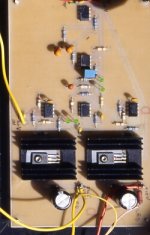
Re: Picture
Attached a picture of a +/- 15V supply for a MC phono amp.
Elso Kwak said:File refuses to upload. What's this? I will try again!
Attached a picture of a +/- 15V supply for a MC phono amp.
Attachments
RAKK DAC price
Just extracted the price from K&K audio
RAKK DAC Kit (requires 12v DC source) $250
I will use battery..but if you need a psu
12v Minimal Reactance Power Supply Kit $79
Needs either
Passive Transformer Output Stage Kit $299
or
Active Differential Tube Output Stage Kit $599
or
Your own design.
PSU for the Active Differential Tube Output stage is
Multi-Minimal Reactance Power Supply Kit (which includes high voltage supply, filament supply and 12v DAC supply for Differential Tube
Output Stage Kit and RAKK DAC Kit) $230
There you have it Hajime...for your budget ...you can get a Top Notch Dac within your budget..
DAC 250
PSU 79
I/V TRANSFORMER KIT 299
= 628.
Add enclosure and various components like on/off switches and you should still be under your 900 dollar budget.
Cheers,
Bas
Another design with schematics
I have a design for a hi-fi audio DAC you may want to checkout. As you can see the circuit board's form factor matches its typical data source.
The theory of operations is here:
XD0
Nine page schematics download is here:
XD0 schematics
By 6-25-2004 I will be posting rev 2.2 of the schematics and the PCB layout.
I have a design for a hi-fi audio DAC you may want to checkout. As you can see the circuit board's form factor matches its typical data source.
An externally hosted image should be here but it was not working when we last tested it.
The theory of operations is here:
XD0
Nine page schematics download is here:
XD0 schematics
By 6-25-2004 I will be posting rev 2.2 of the schematics and the PCB layout.
I guess I have trouble getting too excited about XD0. Correct me if I am wrong, but this is basically the "Cheap 24/96" DAC with more regulators and a different (IC instead of discrete) analog stage. Don't get me wrong, I know local decoupling and regulation can make huge improvements, but when better DIRs and ASRCs have been around for years I can't get excited about CS8420.
It is a little frustrating if one is not into the latest NOS fad...there are few designs that really break new ground. I would consider Guido's VCXO scheme and JWB's in-development DAC (better ASRC, mono mode DACs) to be in the "exciting" category for me.
It is a little frustrating if one is not into the latest NOS fad...there are few designs that really break new ground. I would consider Guido's VCXO scheme and JWB's in-development DAC (better ASRC, mono mode DACs) to be in the "exciting" category for me.
- Status
- This old topic is closed. If you want to reopen this topic, contact a moderator using the "Report Post" button.
- Home
- Source & Line
- Digital Source
- Top-notch DAC.