your links returned this:
you will be surprised at how the insulating varnish can get in between the laminations so that scratches are not an issue as far as i am concerned....
Forbidden
You don't have permission to access /bulk/spreadsheets/tranformerdesign1.ods on this server.
Additionally, a 404 Not Found error was encountered while trying to use an ErrorDocument to handle the request.
you will be surprised at how the insulating varnish can get in between the laminations so that scratches are not an issue as far as i am concerned....
retarded default file permissions in ubuntu 13 to blame. i also removed the space in the filename from the chokecalculator file.
and yes, i'm supprised at just how thin the varnish is.
btw, there isn't supposed to be any. the oxide coating from the factory is engineered to provide the optimum amount of insulation without reducing the stacking factor from the .98 it should be down to .90
and yes, i'm supprised at just how thin the varnish is.
btw, there isn't supposed to be any. the oxide coating from the factory is engineered to provide the optimum amount of insulation without reducing the stacking factor from the .98 it should be down to .90
magnetizing current is inversely proportional to mean magnetic path lenght...https://www.google.com.ph/search?q=...57&sourceid=chrome&espv=210&es_sm=93&ie=UTF-8
so that non scrapless laminates can have smaller or larger depending on actual dimensions for same size center leg...
Thank you Tony, that was excellent for me to reference. By doing a bit more searching, I was able to pin down as to why my calculations, although correct were 30% off. Which leads to the reason you and as well as others have used.........
Thus simplifying the formulas to ensure a cool/stress free design in most if not all builds. I would further add to the fact that my calculations using my 'experimental base' transformer were aproximately 30% on the low side.chapter 5 of RDH4, page 235 (http://www.ax84.com/static/rdh4/chapte05.pdf) gives the formula that i use in my designs and builds,
VA = (A*5.58)^2 volt-amperes
where A is the area under the core in square inches
As I would presume my example transformer although runs relatively warm loaded to 25% and would most likely run much warmer under heavier loading. And most likely hot being loaded to 80% or more. Confirming that manufactures do what they can to get more bang for the $$. Thank you Tony and johansen.so, really, all this wasted time of calculating from archaic formulas is really just.. meh, do i want a 30C temperature rise or 120? can i sell the completed transformer for 6 dollars a pound or 30?
Load being a static value steped through multiple B table with multiple efficiency outputs? Would you have the load as a % of max loading, or would you have it as a static integer?I would like to get my spreadsheet to output a graph of efficiency vs load for various flux densities.

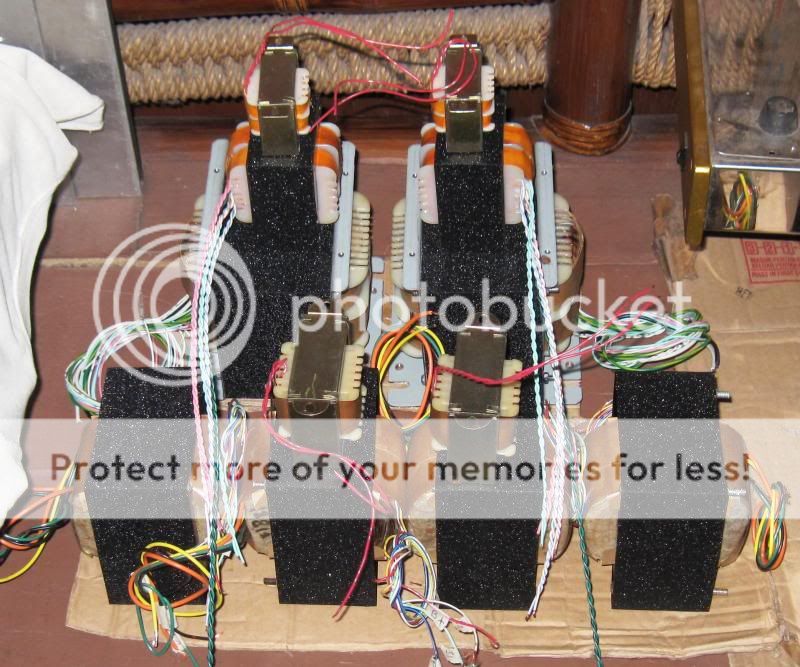
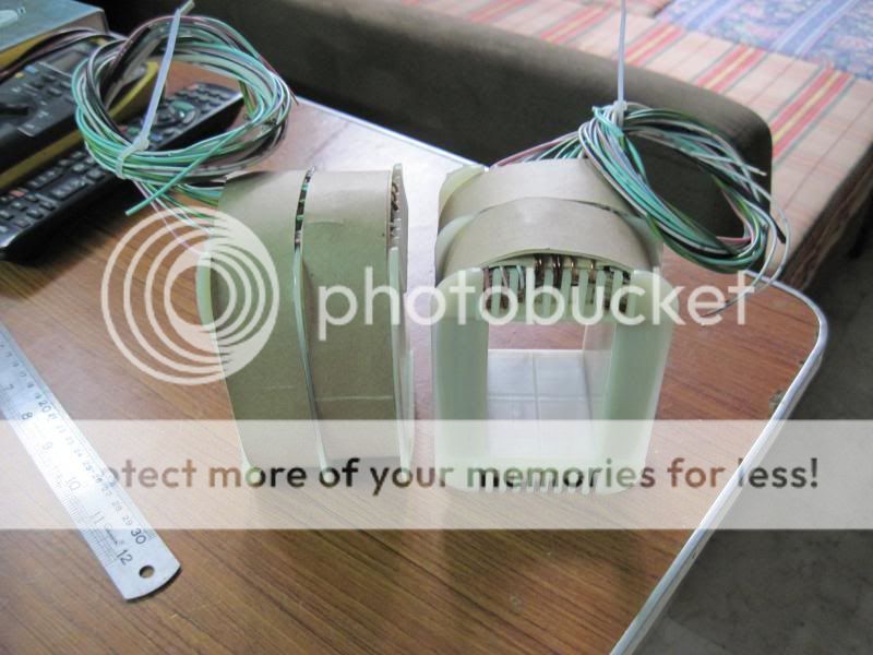
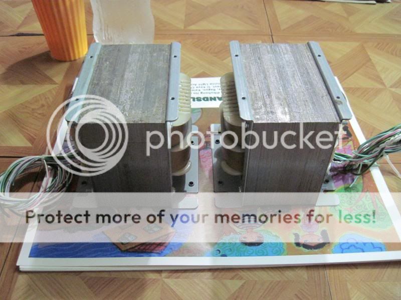
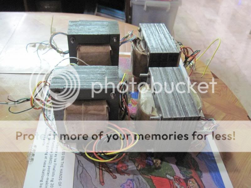
been busy winding traffos for upcoming EL34 parallel pp amp build...
An externally hosted image should be here but it was not working when we last tested it.
An externally hosted image should be here but it was not working when we last tested it.
An externally hosted image should be here but it was not working when we last tested it.
An externally hosted image should be here but it was not working when we last tested it.
AJT Where do you get youe E-I cores from?
from a local vendor, Z11 and M18 cores both 0.35mm thick,
some from metal recycle's, these cores are 0.5mm thick,
AJT,
do you use a different flux for the different thicknesses and types?
yes, if the core material is M6 quality i use 1T,
if low quality i use down to 0.6T
if i do not know where the core came from, i assume it as low quality...
Hi Tony,
Nice to see this thread. I would like to ask for some help. I have a toroid trafo, and I wanted to rewind it but I am not sure what is the VA rating. Here is the dimension,
(od= 4.5 inches, id= 2.5 inches, h= 2 inches).
Thanks
Ren
VA is about 300 to 350...assuming that your dimensions are bare core...
i tend to be conservative in my traffo builds...for EI i seldom went beyond 1T, since EI cores available here in Manila are low quality ones, i operate them at 0.6T average...
i suppose you can get more out of that torroid, but question is at what temperature rise?
if you live in an area where ambient temperatures are in the low 20*C you can operate the traffo more aggressively
, otherwise in our place where ambient temperatures can go as high as 40*C, then you would tend to be conservative....
you should be able to wind the primary with 230-245 turns of 15 awg wire, for 1.6-1.5T
this assumes 120 volt primary?
in our country 230volt is common...
small transformers typically run copper losses at 2-10 fold the no load core loss.
since copper loss follows the inverse of flux squared assuming constant copper volume, well, you can find your own optimal operating point yourself.
but cutting the flux down to 1T to save 2 watts of no load loss, when you're going to burn 15? times that in the copper isn't really smart.
of course leakage flux is a problem, so don't try and run it at 1.8T...
yes, of course its for 120vac. double the turns and add 20% for 50 hz, 18 awg would be more appropriate
Last edited:
- Home
- Amplifiers
- Power Supplies
- Tony's latest traffo DIY build