Btw, what is the average amount of voltage involved in a passive speaker filter ? Is the voltage rating of the capacitor in relation with how much curent can through into it ? Does the quantity is coming from the efficienty of the drivers or the dats of the amp ?
About dielectric, it was perhaps this review ? The "Sound" of Capacitors
For my ears, a mylar cap for instance sounds different from a MKT cap in serie with an aluminium dome driver ! But I really don't know at iso capacitance the datas involved to translate the sound difference into data when talking about 2 caps ! And of course if the corrections made are not good sounding defaults (compensation) ?!
So it's often try & error to finf what can marry well for the whole system (tweaking to "tailor" the final output sound!)
There was a very detailed technical study done years ago that bears the above poster's last statement. It can be found on the web still, I believe. It was called "The Sound of Capacitors".
Cyril Bateman was the author of a series of articles published in the early 2000's in Electronics World Mag. Here is a link to a site where you can download all of his articles.
https://linearaudio.nl/cyril-batemans-capacitor-sound-articles
Thank you & Linear Audio to group the C Batmann papers here.
I already read it. It makes sense as there are measurements. But the measurements don't say all and the study was not pushed far enough imho. The default is the measurement are the origin of the theory and he didn't start from theories or observations to be checked by measurements !
This is different fro a scientific point of view : Maybe correct for ingeeniring but not science !
What happen if you take 20 different caps from very near values or similar (at least from the datasheets) and you got from ears 20 different sonics signature ? Some will be close while not being exactly the same ! And used as compensation in a whole system, it makes sense to choose one over the 19others ! I believe this is mostly the Learning of T Gee and others C Batmann. Indeed some techniologies are from an ingineering point of view better than others but it's impossible to make an universal rating ! For instance the Mundorf bidule sounding better than the AUdyn stuff Y, etc !
I tried maybe for the fun on both analog and digital side of a good dac hundred of caps with close specs and with the same test protocol ! Any "sounds" the same ! Sometimes it's only subtle, sometimes difference are huge from the best subjectvly for the ears as the worst !
IMHO, It needs more things to be measured to be able to predict the results with more security ! Of course lack of time ! Who want to measure and investigate in a lab more than the bigger electrical parameters we have in the datasheets ? No one ! Or maybe it is a scale problem with what we measure in relation with what we hear ? I don't know !
At the end, from my experience at least : the best cap in the datasheet is not always the best cap in the stuff for the sound quality ! ESR/ESL, dissipation factor, voltage/capacitance, dielectric don't tell all ! Or if they tell all we don't know yet how to pick for the best sounding results everytime ! The scope will tell when it sounds bad (big defaults) but never when it sounds better than another (two results coulb be good from a measurement point of view).
Nothing knew : there is asthetic in the way we hear the music and the whole hifi chain is complex ! that's why there are so many people whom like hifi and others whom have good incomes from this !
The sorting of the caps is often a thing who is forgotten or made at minima by the brands because it's time, so cost consuming... they knwo some receipes but it's always a little short... imho, YMMV !
If only we had all the same Hifi Stuffs, we could with Demning Wheel approach with time for the best when it comes to choose caps ! But if caps are very important in the passive parts, this is of course not the only and most important parameter in good sound ! But you CAN NOT give up this "borring choose the best cap her ein this partiular circuit & area" to get the best sounding results at the end ! Fatiguing... but needed !
Last edited:
Bateman's work was important because cap mfgr's weren't spec'ing distortion at all. Even today, caps sole designed and manufactured for audio applications don't have distortion specs.
Bateman was able to find which type of cap construction had the lowest measurable distortion - even though some of them were rediculously low. like 0.0002%!
Bateman was able to find which type of cap construction had the lowest measurable distortion - even though some of them were rediculously low. like 0.0002%!
The capacitor tests for distortion only looked at capacitors that were being used as filters. They had by definition a high AC voltage across them.
There is a whole range of other duties where the AC voltage is virtually zero. The cap tests should not in my opinion be extrapolated to cover these near zero AC voltage duties.
There is a whole range of other duties where the AC voltage is virtually zero. The cap tests should not in my opinion be extrapolated to cover these near zero AC voltage duties.
Russian relativly (the increase its price a lot because of audiophils) cheap K73-16 (mylar) in speaker filter ?
Does it Worth it instead more modern audio capacitors in the same price range ?
I like a lot Mylar with aluminium drivers... as dielectri in oïl despite a little less transparency (détails), at least in the mid area...
Waiting for better stuffs than MiniDSP but still cheap before swapping to active filtering")
Does it Worth it instead more modern audio capacitors in the same price range ?
I like a lot Mylar with aluminium drivers... as dielectri in oïl despite a little less transparency (détails), at least in the mid area...
Waiting for better stuffs than MiniDSP but still cheap before swapping to active filtering
Last edited:
You mean in a speaker filter ?
I never really liked Silmic II at power position (when needed the Silmic (the non-II) where much better imho while a little less transparent) ! I never ever use them in sources or amps (I mean the S II in power application but just DC blocking when needed !)
I guess I shouldn't comment on the Silkic II, the ones I use are the ARS versions. They however sounded soft when used as coupling in both speaker, and low level.
The ARS are similar to the II, (likely RFS) but have a subjectively flatter spectrum with a better midrange. I had tried the silmic II and noticed that certain voices/ranges were simply filtered out completely! Not exactly an ideal part imho, along with a muddy bass.
If by chance ESR is the potential problem that is affecting the 'sound quality' of audio capacitors, then it is possible to alleviate the problem by using multiple capacitors of the same manufactured quality, in parallel, to make up the target value used in the crossover.
By way of explanation, if we have a target value for a capacitor in a crossover of 33uf then that can be made up of 10 x 3.3 uf capacitors in parallel, The effect of this is that although the capacitance is added to the correct value, the ESR of each capacitor is paralleled to the next and the next and so on.
In this case, the total ESR will be the ESR of a single 3.3 uf capacitor divided by 10.
What this means by paralleling one effectively increases the conductive surface area over that of a single 33uF capacitor, thus the ESR of the parallel combination is much less constricting to current flow than a single large capacitor of similar value.
Of course there is a price to be paid for all this, and that is bulk and the total cost of the individual capacitors paralleled as against that of a single large capacitor. But if ESR is what is producing a tonal difference with capacitors then this should make a difference.
C.M
ESR is one of the factor, even not sure it is the most important (for instance Polystyren or Teflon are not always the best choice = ! It is from an engineering point of view but as it's a whole thing than a hifi system, more than often such data is not enough for the choice (idem in electronics devices : amp, dac, etc) !
I surmise also than // capacitor has also an effect on the dissipation factor too which plays on the sound and indeed dissipation has also to see with ESR !
As Andrew pointed out the behavior of a capictor is "harder" to understand (I sumarize with my words and my limited knowledge here !) in a filter !
As the signal is passing in many active & passive devices, the last caps stay a choice to try for a compensation to 'tailor" the sound (that's why the best datas don't worch each time, because it's about aethetic ! We all know sometimes than nice distorsion is nicer to listen to than a clean thin sound for instance !)
Well Nothing new but the price of the expensive audio caps ! MiniDSP and likes have a good future in front of them if the manufacters continue to make so huge margins (and don't tell me than the audiophil market is reducing ! Since Internet there are more diyers than ever )
Sorry for the non technical OT point of view btw ! Not usefull to the discussion ! I still enjoy reading T Gee despite I take it by experience with a grain of salt ! All is about the good choice in each PARTICULAR circuit... 
I surmise also than // capacitor has also an effect on the dissipation factor too which plays on the sound and indeed dissipation has also to see with ESR !
As Andrew pointed out the behavior of a capictor is "harder" to understand (I sumarize with my words and my limited knowledge here !) in a filter !
As the signal is passing in many active & passive devices, the last caps stay a choice to try for a compensation to 'tailor" the sound (that's why the best datas don't worch each time, because it's about aethetic ! We all know sometimes than nice distorsion is nicer to listen to than a clean thin sound for instance !)
Well Nothing new but the price of the expensive audio caps ! MiniDSP and likes have a good future in front of them if the manufacters continue to make so huge margins (and don't tell me than the audiophil market is reducing ! Since Internet there are more diyers than ever
)Sorry for the non technical OT point of view btw ! Not usefull to the discussion ! I still enjoy reading T Gee despite I take it by experience with a grain of salt ! All is about the good choice in each PARTICULAR circuit
... If by chance ESR is the potential problem that is affecting the 'sound quality' of audio capacitors, then it is possible to alleviate the problem by using multiple capacitors of the same manufactured quality, in parallel, to make up the target value used in the crossover.
By way of explanation, if we have a target value for a capacitor in a crossover of 33uf then that can be made up of 10 x 3.3 uf capacitors in parallel, The effect of this is that although the capacitance is added to the correct value, the ESR of each capacitor is paralleled to the next and the next and so on.
In this case, the total ESR will be the ESR of a single 3.3 uf capacitor divided by 10.
What this means by paralleling one effectively increases the conductive surface area over that of a single 33uF capacitor, thus the ESR of the parallel combination is much less constricting to current flow than a single large capacitor of similar value.
Of course there is a price to be paid for all this, and that is bulk and the total cost of the individual capacitors paralleled as against that of a single large capacitor. But if ESR is what is producing a tonal difference with capacitors then this should make a difference.
C.M
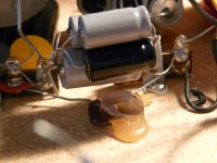
Peter Snell used bundles of NPE caps in his early designs. For example, if he wanted a 16uF cap, he'd bundle four 4uF caps. My guess is he stocked many 4uF caps and used them in different combinations to get the value he wanted. Below is a close up of just one bundle in a Model A speaker crossover. Note the small PET 'drop' cap (bypass?) located at the bottom of the bundle in the picture to help anchor the hot melt glued bundle to the particle board xover board.
Attachments
This may be fine if all the caps were the same value and type. But from what I have heard that mixing the same type/brand of caps with different values, could cause problems such as a phase shift. So for an example, if you wanted to get a 22uF value and used (2) 10uF caps paralleled with a 2uF, this would cause issues and a phase shift. Please correct me if I'm incorrect about this!
I wanted to try the caps that soongsc commented on using the CDE caps with the Vishay MKP1837 bypass cap. One of the values I would need for a tweeter would be a 15uF cap. CDE doesn't offer that value so I would have to use say (3) 4.7uF to get 14.1uF. I still need .9uF to get the correct value, so I could add a 1.0uF and also a .1uF for bypass and get 15.2uF which should be ok? By using this 1uF and .1uF in combination with the (3) 4.7uF caps in parallel, wouldn't I get a phase shift or have issues?
I wanted to try the caps that soongsc commented on using the CDE caps with the Vishay MKP1837 bypass cap. One of the values I would need for a tweeter would be a 15uF cap. CDE doesn't offer that value so I would have to use say (3) 4.7uF to get 14.1uF. I still need .9uF to get the correct value, so I could add a 1.0uF and also a .1uF for bypass and get 15.2uF which should be ok? By using this 1uF and .1uF in combination with the (3) 4.7uF caps in parallel, wouldn't I get a phase shift or have issues?
Last edited:
This may be fine if all the caps were the same value and type. But from what I have heard that mixing the same type/brand of caps with different values, could cause problems such as a phase shift. So for an example, if you wanted to get a 22uF value and used (2) 10uF caps paralleled with a 2uF, this would cause issues and a phase shift. Please correct me if I'm incorrect about this!
I wanted to try the caps that soongsc commented on using the CDE caps with the Vishay MKP1837 bypass cap. One of the values I would need for a tweeter would be a 15uF cap. CDE doesn't offer that value so I would have to use say (3) 4.7uF to get 14.1uF. I still need .9uF to get the correct value, so I could add a 1.0uF and also a .1uF for bypass and get 15.2uF which should be ok? By using this 1uF and .1uF in combination with the (3) 4.7uF caps in parallel, wouldn't I get a phase shift or have issues?
Short answer is No.
'Phase shift' is a shift in time. (Signal reversal .....is not 'Phase shift'.)
Any paralleled value of pure capacitance can be added together as a whole without there being any phase shift between capacitors. Any resistance introduced however will produce a slight phase shift, which by its nature is inaudible unless a substantial change in amplitude of the signal occurs as it passes through the combination of capacitors.
The phase shift introduced by ESR is negligible at low frequencies where the capacitive reactance of the capacitor is very high, but as the frequency rises to a point where the capacitive reactance becomes low and comparable to that of ESR the phase shift is changed significantly.
Whether this change in phase is audible is debateable, generally accepted as 'No', but as the capacitance reactance (Xc) is now low at this high frequency a small value of voltage is now dropped across the ESR of the capacitor and this may become audible if the ESR is particularly high. This is all highly subjective.......thus the arguments. So it is likely that the audible differences between capacitors is likely to occur at high frequencies, if at all, but that will depend on the subjective experience of the listener, their hearing and the capacitor types used.
Now the combined value ofthe ESR of paralleled capacitors of the same make but of different values will be much less than that of a single capacitor of the same totaled value. It works with the same formula as with parallel resistors .
So a lower ESR is much preferred over that of a higher one simply because of the slightly lower attenuation at high frequencies, particularly when working into a low impedance load such as a tweeter, or an upper midrange.
C,M
Last edited:
This may be fine if all the caps were the same value and type. But from what I have heard that mixing the same type/brand of caps with different values, could cause problems such as a phase shift. So for an example, if you wanted to get a 22uF value and used (2) 10uF caps paralleled with a 2uF, this would cause issues and a phase shift. Please correct me if I'm incorrect about this!
I wanted to try the caps that soongsc commented on using the CDE caps with the Vishay MKP1837 bypass cap. One of the values I would need for a tweeter would be a 15uF cap. CDE doesn't offer that value so I would have to use say (3) 4.7uF to get 14.1uF. I still need .9uF to get the correct value, so I could add a 1.0uF and also a .1uF for bypass and get 15.2uF which should be ok? By using this 1uF and .1uF in combination with the (3) 4.7uF caps in parallel, wouldn't I get a phase shift or have issues?
What kind of phase shifts are you referring to? electrical or, acoustical?
This may be fine if all the caps were the same value and type. But from what I have heard that mixing the same type/brand of caps with different values, could cause problems such as a phase shift. So for an example, if you wanted to get a 22uF value and used (2) 10uF caps paralleled with a 2uF, this would cause issues and a phase shift. Please correct me if I'm incorrect about this!
I wanted to try the caps that soongsc commented on using the CDE caps with the Vishay MKP1837 bypass cap. One of the values I would need for a tweeter would be a 15uF cap. CDE doesn't offer that value so I would have to use say (3) 4.7uF to get 14.1uF. I still need .9uF to get the correct value, so I could add a 1.0uF and also a .1uF for bypass and get 15.2uF which should be ok? By using this 1uF and .1uF in combination with the (3) 4.7uF caps in parallel, wouldn't I get a phase shift or have issues?
In Taiwan, they have 15uF
http://www.yoson.com/yoson/index.php?route=product/product&product_id=8510
https://m.ruten.com.tw/goods/show.php?g=21507490209986
Sent from my iPhone using Tapatalk
Last edited:
What kind of phase shifts are you referring to? electrical or, acoustical?
Not really sure as I was told this by a friend that designs tube amps and other electronic audio components!
- Status
- Not open for further replies.
- Home
- Design & Build
- Parts
- Tony Gee's Capacitor page updated..