variation on the theme...
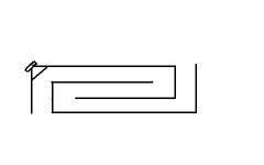
here (I hope) is a crude attached drawing based on the Half Square Antenna design that was mentioned by DKJ in the Acoustic Wave Cannon thread. I have folded the long 1/4 wave section into three to make the whole thing more compact. This causes the two (one at each end of the 1/4 wave line section) 1/8 wave sections to exit at 180 degrees to each other rather than both dropping as Dennis discribed. I am not sure if either of these two changes will have a negative impact or not. The driver loads the line in the top left hand corner firing into both the long 1/4 wave section as well as the shorter 1/8 wave section.
The idea is that the Half Square line will have four distinct nodal points of resonance and so produce output over a wider band than the cannon would with its three nodes. The cross section of the line can range from half driver Sd to 100% of driver Sd with half area yielding the smoothest response and 100% area yielding the greatest output (most ripple).
I have also attached a link to the thread page where DJK discribes the idea. I woud be interested in comments on this idea. Regards Moray James.
http://www.diyaudio.com/forums/showthread.php?s=&threadid=9501&perpage=10&pagenumber=19
Attachments
Greets!
Vaguely, I file thread responses by driver make/model, which I don't recall yours.
How do you know the TOP has a 1:2 taper? What's a PB12?
I researched the G-H some time ago, but can't find my notes, though in a nutshell, in theory I can get superior performance overall in a smaller bulk using a corner loaded PWT now that low Fs, high Xmax/power handling drivers and megawatt amps are available at a reasonable price. Still, a low pass filtered resonant cavity can be a 'moving'") experience if you have a basement, attic, or similar size volume available to couple it to.
experience if you have a basement, attic, or similar size volume available to couple it to.
GM
Vaguely, I file thread responses by driver make/model, which I don't recall yours.
How do you know the TOP has a 1:2 taper? What's a PB12?
I researched the G-H some time ago, but can't find my notes, though in a nutshell, in theory I can get superior performance overall in a smaller bulk using a corner loaded PWT now that low Fs, high Xmax/power handling drivers and megawatt amps are available at a reasonable price. Still, a low pass filtered resonant cavity can be a 'moving'
experience if you have a basement, attic, or similar size volume available to couple it to.GM
Re: variation on the theme...
Greets!
Hmm, all I see is a folded up offset driven 1/2 WL pipe since the driver isn't in series like a BWC........... Anyway, a half square wave sub duty pipe will be pretty big since the total pathlength will ideally need to be 1 WL of Fs (minus end corrections).
GM
Greets!
Hmm, all I see is a folded up offset driven 1/2 WL pipe since the driver isn't in series like a BWC........... Anyway, a half square wave sub duty pipe will be pretty big since the total pathlength will ideally need to be 1 WL of Fs (minus end corrections).
GM
I built something akin to a "Tapped Horn" but for midrange. While working on my Unity horn, I was curious if the tapped horn concept applied to mids as well as subs. If you'd like to see the results, I'm posting them here:
Tapped Midrange Horn
Tapped Midrange Horn
An externally hosted image should be here but it was not working when we last tested it.
I'm the guy that cut my wood based on the transflex/top design first and then tried to find a driver that would work in the line. You helped me with some Dayton sims and I chose the 15" Quatro in the "Please help with MJK's alignment tables" thread.
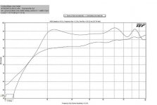
The PB12, although I have little info, seems to be an earlier variant of the TOP. It is (I think) exactly the same size as the TOP but it is tuned a bit higher and probably uses the same driver. I believe (although I'd have to check again) that this very thread talks about the PB12 and there is picture of the mouth, which is open on three sides of the box. This picture seems to show evidence that there is a taper going on, somewhere in the neighbourhood of 1:2. It may be worth noting that until recently Danley's TOP writeup on his website used the PB12 frequency response chart instead of one from a TOP. I saved both the old and new charts. The newer TOP bottom end is not as strong, but extends much lower than the PB12 but the PB12 top end is a bit more spiky. This all leads me to believe that the TOP taper is somewhere between 1:2 and 1:1 but nowhere near 2:1, like my box currently is.
Since the taper is easily reversible in my box, I decided to opt for the lower tuning just to try it. It works very well from 16 - 40 hz but needs to be crossed over above that. If I were to measure my output AFTER reversing my taper, I would expect my frequency response chart to look exactly like the PB12's, which I will try to post below because it has been replaced with the proper TOP response chart and is no longer on the Danley site.
Anyway, sorry for hijacking this thread (although I suppose technically it is about the TOP). I just have one question. What is PWT? Does it have something to do with passives? That is the only small way I know of to get low.
Attachments
Greets!
Ah! No wonder I couldn't find it, it wasn't in a TOP/whatever thread. Since you can't XO higher, the Transflex/TOP type of front-of-driver loading isn't working properly.
OK, not familiar with the PB12, though I do have an early DTS-20 spec sheet that has the same FR plot you posted. Just looking at the two different plots, the early one looks like something a straight pipe would generate, whereas the current one looks more like a pipe horn.........
Anyway, a PWT = plane wave tube, which is normally used to measure a driver's power response, but can make for a seriously high SQ cab that's somewhat better than an IB, though not quite as good as an acoustically huge for the BW hyperbolic horn.
GM
Greets!
Well, one designed for testing drivers is a bit more complex than what few I've built, which is a 2:1 CR 1/2 WL of Fs sealed pipe, so CSA = driver Sd/2 and L = ~13,560"/2/Fs, with minimal stuffing along its length. For high SQ to 10 Hz though, the driver Fs needs to be < 14 Hz, so efficiency will suffer. Then again, our hearing acuity is such that below ~35 Hz we don't have any of note, so any good quality true sub driver will suffice IMO if it has enough linear power handling to please.
Based on the small driver ones I've built, this thing will generate some serious pressure at linear rated power, so rigid, leak free construction is paramount to proper performance.
GM
possible folding for TH112 and H115...
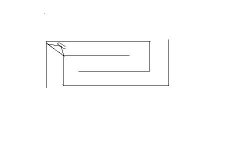
Here is a possible folding config. for the Danley box. I have shown the first 1/4 section of the line equal to driver Sd but this section could just as easily taper to So=0. A further alternate would be to have the line start at So=Sd. Regards Moray James.
Here is a possible folding config. for the Danley box. I have shown the first 1/4 section of the line equal to driver Sd but this section could just as easily taper to So=0. A further alternate would be to have the line start at So=Sd. Regards Moray James.
Attachments
Long pipe...
I just figured 24 ft. for a driver with an Fs of 23 Hz. So the driver goes right at the end? The other end should be what, 1/4 to 1/2 wave away from the driver? Won't fit in the trunk but there are lots of car drivers that would fit in one of these. Sounds like a natural for construction pipe under ground. There must be rules for reflections when folding something like this but they have fallen out of my head. Interesting if room permits. Regards oray James.
I just figured 24 ft. for a driver with an Fs of 23 Hz. So the driver goes right at the end? The other end should be what, 1/4 to 1/2 wave away from the driver? Won't fit in the trunk but there are lots of car drivers that would fit in one of these. Sounds like a natural for construction pipe under ground. There must be rules for reflections when folding something like this but they have fallen out of my head. Interesting if room permits. Regards oray James.
"The driver loads the line in the top left hand corner firing into both the long 1/4 wave section as well as the shorter 1/8 wave section."
Thanks for the picture correction, I was going to mention but thought maybe you had a different idea going there. But doesnt this actually load into the 1/8 stup and a 7/8 section?
To work properly, I believe the lengths have to be a 1/4w stub and 3/4w section with the exits 1/2w apart.
This way you get a resonance from the left pipe at 1/4w, an addaitve output from both 'ports' at 1/2w, resonance on the right at 3/4w, and a reduced addative output at 1w from both.
(or at least thats the theory)
The trick is making the responce of each 'port' wide enough, or the reasonant peaks close enough together to blend into a relatively flat output from 1w to 1/4w.
Re: Re: variation on the theme...
Thanks GM. So my 19hz Tempests need almost a 30ft line of a constant CSA of 1/2 Sd. What about the backside of the driver, just open to the room? Explosions don't have much SQ, so my primary concern is output in the low teens or lower.
GM said:Greets!
Hmm, all I see is a folded up offset driven 1/2 WL pipe since the driver isn't in series like a BWC........... Anyway, a half square wave sub duty pipe will be pretty big since the total pathlength will ideally need to be 1 WL of Fs (minus end corrections).
GM
Thanks GM. So my 19hz Tempests need almost a 30ft line of a constant CSA of 1/2 Sd. What about the backside of the driver, just open to the room? Explosions don't have much SQ, so my primary concern is output in the low teens or lower.
as far as I know...
the idea was to have an acoustic version based upon the antenna theory. And yes Dennis implied that this arrangement would add one additional resonant peak to the pipe making the band wider (from three to four). I was under the impression that it was 1/4 - 1/2 - 1/4 wave sections so a total of one wave length . That is huge and so I was folding to try to make the thing compact.
The design example that Dennis gave for the small 4 inch driver with the 85 Hz Fs was 20" - 40" - 20" which is clearly 1/8 - 1/4 - 1/8. so from that I figured that the lengths could be reduced to the same ratio and still workas per the antenna theory. I would like to hear from Dennis on this one. The cannon is interesting but big, but not as big as the PWT just mentioned by GM. These are in the land of built in to stay in systems.
I came up with a possible folding for Tom's Th 112 and 115 but for the life of me I cannot get it to uplink don't know why. Regards Moray James.
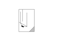
Reguardless of the length of the pipe, the frequency at which it will resonate is 1/4w.
The 20" segment will resonante at 170Hz.
The 60" segment will resonante at 42Hz.
At 85Hz the output from both segments will be much reduced compared to those resonant levels, but since they are 180 degrees out of phase, and 180 degrees apart in spacing, the result will be addative.
The same should occur, though at a reduced level, at 21Hz.
(image not to scale of any kind)
While this layout is basically a form of 3508 wave cannon, the same kind of 1/4w phase addition/subtraction occurs inside Danley's TOP.
Yes, they will be large.
The 20" segment will resonante at 170Hz.
The 60" segment will resonante at 42Hz.
At 85Hz the output from both segments will be much reduced compared to those resonant levels, but since they are 180 degrees out of phase, and 180 degrees apart in spacing, the result will be addative.
The same should occur, though at a reduced level, at 21Hz.
An externally hosted image should be here but it was not working when we last tested it.
(image not to scale of any kind)
While this layout is basically a form of 3508 wave cannon, the same kind of 1/4w phase addition/subtraction occurs inside Danley's TOP.
Yes, they will be large.
Re: Re: Re: variation on the theme...
Greets!
Hmm, did you mean to quote post #88? Anyway, you're welcome!
Yeah, it's going to be big since even Dr. Bose can't shrink a long WL, though his marketing gurus would have you believe otherwise. Right, it's just an end loaded sealed pipe. Considering the BW though, the Tempest's 19 Hz Fs makes it a near ideal B@#$ WC driver except for its large Sd since this BP's alignment has only a ~two octave span (~9.9 - 38 Hz) if kept either straight or folded such that the exit's outputs help rather than audibly degrade its FR. Unfortunately, it will be considerably larger than the PWT at ~37 ft long.

GM
johninCR said:
Thanks GM. So my 19hz Tempests need almost a 30ft line of a constant CSA of 1/2 Sd. What about the backside of the driver, just open to the room? Explosions don't have much SQ, so my primary concern is output in the low teens or lower.
Greets!
Hmm, did you mean to quote post #88? Anyway, you're welcome!
Yeah, it's going to be big since even Dr. Bose can't shrink a long WL, though his marketing gurus would have you believe otherwise. Right, it's just an end loaded sealed pipe. Considering the BW though, the Tempest's 19 Hz Fs makes it a near ideal B@#$ WC driver except for its large Sd since this BP's alignment has only a ~two octave span (~9.9 - 38 Hz) if kept either straight or folded such that the exit's outputs help rather than audibly degrade its FR. Unfortunately, it will be considerably larger than the PWT at ~37 ft long.
GM
Re: Long pipe...
Greets!
Correctomundo!
1/2 WL away.
Yep, mine were all built using drain pipe. You want the harmonics suppressed, so folds only need to maintain the CSA through the bend.
GM
moray james said:So the driver goes right at the end?
The other end should be what, 1/4 to 1/2 wave away from the driver?
Sounds like a natural for construction pipe under ground. There must be rules for reflections when folding something like this........
Greets!
Correctomundo!
1/2 WL away.
Yep, mine were all built using drain pipe. You want the harmonics suppressed, so folds only need to maintain the CSA through the bend.
GM
moray james said:the idea was to have an acoustic version based upon the antenna theory. And yes Dennis implied that this arrangement would add one additional resonant peak to the pipe making the band wider (from three to four). I was under the impression that it was 1/4 - 1/2 - 1/4 wave sections so a total of one wave length . That is huge and so I was folding to try to make the thing compact.
The design example that Dennis gave for the small 4 inch driver with the 85 Hz Fs was 20" - 40" - 20" which is clearly 1/8 - 1/4 - 1/8. so from that I figured that the lengths could be reduced to the same ratio and still work as per the antenna theory. I would like to hear from Dennis on this one. The cannon is interesting but big, but not as big as the PWT just mentioned by GM. These are in the land of built in to stay in systems.
I came up with a possible folding for Tom's Th 112 and 115 but for the life of me I cannot get it to uplink don't know why. Regards Moray James.
Greets!
Hmm, the link in post #90 works for me. Anyway, it's certainly one way to fold them.
Not so, for a given driver Fs, they are virtually the same, with the BWC shorter only by its terminus's end corrections, though these are offset some/all by the in-line driver 'box', assuming you bother to factor these in.
When you mentioned DJK's analogy of the BWC being based on 'half square' antenna theory/85 Hz driver example recently, I just accepted it at face value due to who said it and answered your Qs based on the info presented without doing any research.
Since you keep bringing it up though, I did a bit of 'due diligence' and not surprisingly it does indeed conform to 1/2 square antenna folding requirements with the short pipe being 1/4 the total pipe's 1 WL length (Fp) and with 1/4 - 1/2 - 1/4 WL fold spacing, or in this case, 170, 340, (2) 680 Hz respectively.
Anyway, it's not a good idea IMO to think of a resonant pipe folding scheme in these terms, and especially as 1/8-1/4-1/8 WLs, so let's pick the BWC apart to hopefully get a better 'feel' for these things and how he arrived at his alignment.
The BWC is a nominally two octave bandpass (BP) device consisting of two 1/4 WL pipes attached to the driver that are 3 ft (36") and 9 ft (108") long, so using your 13,489.5"/sec SoS:
total pipe length = Fp = 13489.5/4/(36+108) = 23.42 Hz
The patent notes that a smoother performance can be had by using a driver that has a Fs = 1/2 WL of the total tube length (Fp), so ideally its Fs = 13489.5/2/144 = 46.84 Hz, or 2*Fp.
The patent refers to the short, long pipes as 1/4 WL and 3/4 WL that sum to 1 WL since it has a 1:3 pipe length ratio, but we're dealing with a 1/4 WL system, so in reality:
1/4 WL short front pipe = (1/4*1/4) = 1/16 WL of Fp = 13489.5/16/23.42 = 36"
Fh = 13489.5/4/36 = 93.68 Hz
1/4 WL long rear pipe = (1/4*4/3) = 3/16 WL of Fp = 13489.5/5.333/23.42 = 108"
Fl = 13489.5/4/108 = 31.22 Hz
Making the resonant 'chain': ~23.42, 31.22, 46.84, 93.68 Hz, with 0.415/0.585/1.000 octave spreads for this straight BWC, or a two octave bandpass (BP) alignment centered on the driver's Fs.
Enhancing it with 'half square' antenna folding:
For smoothest response/broadband gain we want the two openings 1/2 WL of the total pipe length (Fp) apart = (1/2*1/4) = 1/8 WL of Fp:
13489.5/8/23.42 = 72"
13489.5/72 = 187.36 Hz
Since it's 144" long, the 'legs' will be (144-72)/2 = 36" long.
Rounding out our resonant 'chain': ~23.42, 31.22, 46.84, 93.68, 187.36 Hz, we wind up with 0.415/0.585/1.000/1.000 octave spreads.
Viewed by some others, this would be a 13489.5/2/72 = 93.68 Hz 1/2 WL beam with two 93.68 Hz 1/4 WL 'legs', which seems to me a totally wrong way to describe these since it does nothing but confuse/mis-inform folks who aren't already at least somewhat familiar with the two distinctly different systems. As always though, YMMV.
OK, in light of the above, let's see if DJK's 85 Hz 4" driver pipe design conforms with a 40" 'beam' and 20" 'legs':
total pipe length = Fp = 13489.5/2/85 = 79.35"
Looks like we need a SoS adjustment: 80"/79.35" = 1.0082*13489.5" = 13,600":
total pipe length = 13600/2/85 = 80"
Fp = 13600/4/80 = 42.5 Hz
short pipe = 13600/16/42.5 = 20"
Fh = 13600/4/20 = 170 Hz
long pipe = 13600/5.333/42.5 = 60"
Fl = 13600/4/60 = 56.67 Hz
1/2 WL 'legs' spacing = 13600/8/42.5 = 40"
13600/40 = 340 Hz
Since it's 80" long, the 'legs' will be (80-40)/2 = 20" long.
Making the resonant 'chain': ~42.5, 56.67, 85, 170, 340 Hz, with 0.415/0.585/1.000/1.000 octave spreads.
Works for me, so substitute whatever SoS and driver Fs you prefer, or if you want a particular BW, then choose the driver Fs that most closely is either one or two octaves (if folded) below Fh and figure the rest.
Of course these are all heavily rounded off dims since the bend lengths, driver cab Vb, and end corrections aren't factored in, but it's close enough for an inexpensive computer system or true sub duty that's below our acute hearing BW. With one octave resonant spreads in the mids of this alignment though, adding the folds for the extra BW doesn't seem like a good plan to me, but as always, YMMV.
GM
- Status
- This old topic is closed. If you want to reopen this topic, contact a moderator using the "Report Post" button.
- Home
- Loudspeakers
- Subwoofers
- Tom Danley's TOWER OF POWER