While I agree that a tapered divider would seem the obvious choice. I think Danley's version is built similar to this....
Walts Stepped Horn
With the driver located near to the 'step'.
While the current pictures at Danley's site make it difficult/impossible to see. In previous pictures one could see the dividing wall through the port to be straight. In fact early renderings showed the port to 'wrap' around 3 sides of the cabinet. Now reduced to a single port, probably to allow for flush mounting in a wall.
A stepped layout would make bracing far simpler, and more akin to mass production as well.
Relax said:I think my post was deleted, but I was wondering if anyone has built a TL the same size as a tapped line. Then try the driver in the two positions to see differences?
It would be a rather simple way to see if they are close enough to be modeled the same.
Hi Relax
Here is an idea for you.
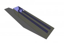
The driver in a standard enclosure on the same end as the port gives you a traditional t-line.
A modified enclosure and on the opposite end gives the "experimental" design.
The end opposite the driver /enclosure would then be capped off.
The unit is 60" x 12" x 12" and is tuned to 17-18hz.
You will need a 50hz 4th order xover for such a low tuning...
Traditional...
Attachments
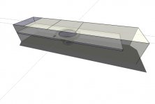
The same 16' tuned pipe with the driver / enclosure on the other end.
The front of the driver fires into the tuned pipe 4' from the sealed end.
The rear of the driver fires into the tuned pipe 4' from the open end.
The end opposite the driver /enclosure is capped off...
The front of the driver fires into the tuned pipe 4' from the sealed end.
The rear of the driver fires into the tuned pipe 4' from the open end.
The end opposite the driver /enclosure is capped off...
Attachments

Tehrasha said:While I agree that a tapered divider would seem the obvious choice. I think Danley's version is built similar to this....
Walts Stepped Horn
With the driver located near to the 'step'.
While the current pictures at Danley's site make it difficult/impossible to see. In previous pictures one could see the dividing wall through the port to be straight. In fact early renderings showed the port to 'wrap' around 3 sides of the cabinet. Now reduced to a single port, probably to allow for flush mounting in a wall.
A stepped layout would make bracing far simpler, and more akin to mass production as well.
Thank you for your feedback.
Yes, I too have looked at all the the posts / pics regarding this subject.
My SKETCHUP is based on all of that information and actual pictures of the unit.
Also, an email specifically mentions that it is tapered.
In fact early renderings showed the port to 'wrap' around 3 sides of the cabinet. Now reduced to a single port, probably to allow for flush mounting in a wall
AFAIK, the port exits from the side, or optionally exits from the bottom
Walt's design is "close" (as I am sure you have seen).
Walt mentions he is not "down 3db at 16hz", however (the TOP published specs).
I believe Walt needs to go to a longer pipe and / or smaller port.
Regards...
What lead you guys to the conclusion that the pathway is tapered at all. The pic I saw which is no longer available looked to me like a constant size pathway, and that Danley's design is just an offshoot of the 1950's Jensen Transflew. The driver is just in a different location. Wouldn't this make it some type MLTL ?
Sorry qi, been a bit busy to reply. Certainly your model feels aesthetically correct with the sloped line, rather than stepped, and I'm sure to improve on the Transflex it has to be significantly different, unless the patent purely applies to the method of calculation. I think it's safe to assume that the driver is in the middle of the enclosure, otherwise why go to the effort of cutting an access hole half way down. Unfortunately, my PC measurement system is inoperative at the moment, otherwise I might build a test cab to experiment with.
johninCR said:What lead you guys to the conclusion that the pathway is tapered at all. The pic I saw which is no longer available looked to me like a constant size pathway, and that Danley's design is just an offshoot of the 1950's Jensen Transflew. The driver is just in a different location. Wouldn't this make it some type MLTL ?
That's exactly what I thought, but an email I read specifically mentions that it is tapered.
My original SKETCHUP...
Attachments
I've been trying to decide what to build as a sub for a false stage under my projector screen. I'm thinking that trying this thing with 10hz tuning and 4 segments is the way to go. I have a few 15's to try, all with dual VC's, so I use RDO to adjust the Qts and can even try isobarik if it's too sloppy or it acts like the total air volume is too small. Do you think 4 times the terminus area that Danley uses makes sense to go an octave lower, or is double the distance around his terminus the right number, or neither?
What about bracing? Is it ok to divide pipe pathways in half ?
Any input is greatly appreciated.
What about bracing? Is it ok to divide pipe pathways in half ?
Any input is greatly appreciated.
My two cents...
I would model it in MJK as a regular straight t-line
Optimize the model with stuffing as usual
Use those specs
Substitute this new technology for the stuffing (ie., no stuffing)
Center bracing is certainly a way to go (dowels are often used)
Just make sure the total CSA inner dimension is to spec
I personally would tune to 15hz and xover at 40hz
10hz tuning is WAY LOW (as I am sure you know)
With 10hz tuning where would you xover?
Qi,
The only benefit I see to going bandpass is that you can make as much room for the driver as you like. Danley's obviously has the driver "tapped" into the midpoint of the pipe.
I think the BP would have problems:
1. Huge chambers are needed for low tuning, otherwise how are you going to introduce LF into the line. I don't believe that sizes for CC's of horns is applicable here.
2. Excursion- You probably give up the cone control of the center tapped alignment.
My main question is the size of the terminus needed. With 1/4 loading is there a guideline for terminus size. With the driver tapped in the line it's like 2 driver Sd's, so is 2xSd to 2.5xSd the right size? Danley's looks to be at most 2xSd, since he has a 10" in there.
This is for HT and many movies have output 10hz and below, so I want to reproduce it. I have the space and plenty of drivers, so it's this or a big iso loaded 6th order BP, or a big sealed box with a bunch of subwoofers and a Linkwitz transform to flatten it out (but I'd need to buy about 5kw of power and put in an extra power run). If the Tower of Power goes up to 100hz, then 50hz isn't asking too much since I want an octave deeper extension, however, my mains are fine to 30hz and ideally I'd like to cross right at my lowest room mode just below 30hz.
We're only talking semantics here.
I am still referring to the designs I have rendered / posted.
Since I have no clue about your driver, this is just a WAG
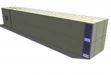
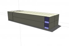
15" driver tuned to 10hz...
339" pipe, or four 85" x 7" x 15" lines (inner dimensions)
CSA (and port size) is 7" x 15"
Box size 16.5" x 32" x 102"
Here is a rough SKETCHUP for your 15" driver...
I am still referring to the designs I have rendered / posted.
Since I have no clue about your driver, this is just a WAG
15" driver tuned to 10hz...
339" pipe, or four 85" x 7" x 15" lines (inner dimensions)
CSA (and port size) is 7" x 15"
Box size 16.5" x 32" x 102"
Here is a rough SKETCHUP for your 15" driver...
Attachments
johninCR
Actually he uses a beefed 12" driver
I assume from other posts of yours, that you are using your Tempest 15
Using Tempest 15 T/S specs...
Fs 18.8hz
Qts .39
Vas 11.2 cu ft
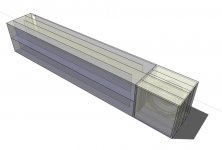
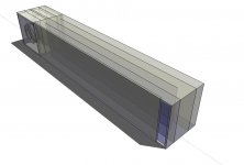
Tuned to 10hz (using 3/4" void-free plywood)...
CSA 4.5" x 19.5" (88 sq in)
Each of the four t-line segments 85" x 4.5" x 19.5 (inner dims)
Port size 4.5" x 19.5" (inner dims)
Two ports joining driver / enclosure to pipe 4.5" x 19.5" (each -- inner dims)
Outer box dimensions 22" x 22" x 102"
With these dimensions it will look much more like this SKETCHUP...
My main question is the size of the terminus needed. With 1/4 loading is there a guideline for terminus size. With the driver tapped in the line it's like 2 driver Sd's, so is 2xSd to 2.5xSd the right size? Danley's looks to be at most 2xSd, since he has a 10" in there.
Actually he uses a beefed 12" driver
I assume from other posts of yours, that you are using your Tempest 15
Using Tempest 15 T/S specs...
Fs 18.8hz
Qts .39
Vas 11.2 cu ft
Tuned to 10hz (using 3/4" void-free plywood)...
CSA 4.5" x 19.5" (88 sq in)
Each of the four t-line segments 85" x 4.5" x 19.5 (inner dims)
Port size 4.5" x 19.5" (inner dims)
Two ports joining driver / enclosure to pipe 4.5" x 19.5" (each -- inner dims)
Outer box dimensions 22" x 22" x 102"
With these dimensions it will look much more like this SKETCHUP...
Attachments
qi said:
AFAIK, the port exits from the side, or optionally exits from the bottom
I was referencing the early version of the TOP, the PB12 which had a port which wrapped around the base. The shape of the port suggested to me that maybe the divider was stepped, but I suppose the taper would be so gentle as to appear straight with only that much of it exposed.
An externally hosted image should be here but it was not working when we last tested it.
Walt's design is "close" (as I am sure you have seen).
Walt mentions he is not "down 3db at 16hz", however (the TOP published specs).
I believe Walt needs to go to a longer pipe and / or smaller port.
Totally agree that Walt needs to go longer to reach the magic 16Hz, but even the TOP doesnt go quite that far. The PDF reads -5dB @18Hz -10dB@15Hz.
Interestingly, according to the PDF brochures, the DTS20 has 1dB more output than the PB12 while all other parameters remain the same. So the port size/shape/location must be very important.
The DTS also appears to have a flatter responce at the low end than the PB12, while the PB12 has a flatter responce overall.
Hello,
I have build the 'stepped' horn as you call it. It is about half the size of a DTS-20 so therefore does not go as low. It plays very powerfull down to 30Hz. It sounds good, but not as good as the Punisher horn I used before.
As far as my reasoning goes with my cabinet: With the driver at the end of the horn in the mouth the driver is exposed to the free air so the pressure is always very low at that point. Therefore I suspect my design to work as a normal rearloaded horn. My measurements seem to indicate this.
I think for the tapped horn it is important to make a good match between driver and cabinet. The Ciare 12.00SW I used probably doesn't need a tapped horn at all. But a driver such as Eminence LAB-12 probably does. This depends on whether you get a hole in the response when using an under sized mouth. The tap should fill this hole.
That where my 2 cents.
Best regards,
Walt
Tehrasha
Actually, if you go to the bottom of that same PDF, this is what you will find.
What I was referencing...
Totally agree that Walt needs to go longer to reach the magic 16Hz, but even the TOP doesnt go quite that far. The PDF reads -5dB @18Hz -10dB@15Hz.
Actually, if you go to the bottom of that same PDF, this is what you will find.
What I was referencing...
Attachments
qi said:
Actually, if you go to the bottom of that same PDF, this is what you will find.
What I was referencing...
That makes much more sense. +/-3dB across the passband and -3dB @ 16Hz are VERY different things.
")
- Status
- This old topic is closed. If you want to reopen this topic, contact a moderator using the "Report Post" button.
- Home
- Loudspeakers
- Subwoofers
- Tom Danley's TOWER OF POWER