Did you go through the checklist in the User Guide for the TPA3255EVM for jumpers and switch settings for the mode you selected (BTL, PBTL, SE, DIFF, etc.) before powering up the amp?
Also, it would help to connect the TPA3255EVM ground connection (between speaker binding posts) to the ground connection on your power supply.
Also, it would help to connect the TPA3255EVM ground connection (between speaker binding posts) to the ground connection on your power supply.
Last edited:
I tried to search the thread to see if these amateurish questions answered already.
I have received two EVM boards and decided to go ahead with Dual MONO. I am little bit confused about PBTL setting.
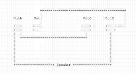
I followed the User guide and understood the jumper settings to change the mode. But I Would like to confirm if my understanding is correct regarding shorting the Speakers o/p terminals (OutA with OutC and OutB with OutD) to run each board in PBTL mono mode.
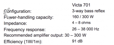
2nd question is to understand if I am really going to get any benefit by using two boards in PBTL mode. My speaker's impedance is given as 4-8 ohm (not sure why it's not given as single value). The stock inductors are ok to run in my setup?
I have received two EVM boards and decided to go ahead with Dual MONO. I am little bit confused about PBTL setting.
I followed the User guide and understood the jumper settings to change the mode. But I Would like to confirm if my understanding is correct regarding shorting the Speakers o/p terminals (OutA with OutC and OutB with OutD) to run each board in PBTL mono mode.
2nd question is to understand if I am really going to get any benefit by using two boards in PBTL mode. My speaker's impedance is given as 4-8 ohm (not sure why it's not given as single value). The stock inductors are ok to run in my setup?
Attachments
Last edited:
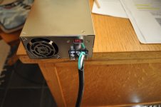
My connections, set on 115v
Hopefully you don't have your wires crossed
")
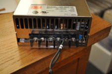
Things I would check out...
120 volts between pins 1 and 2 (live and neutral).
Connectivity between pin 1 (live) and the narrow spade prong on the male side of the power cord.
Connectivity between pin 2 (neutral) and the wide spade prong on the male side of the power cord.
Connectivity between pin 3 (ground) and the semi-circle prong on the male side of the power cord.
Mike
I tried to search the thread to see if these amateurish questions answered already.
I have received two EVM boards and decided to go ahead with Dual MONO. I am little bit confused about PBTL setting.
I followed the User guide and understood the jumper settings to change the mode. But I Would like to confirm if my understanding is correct regarding shorting the Speakers o/p terminals (OutA with OutC and OutB with OutD) to run each board in PBTL mono mode.
2nd question is to understand if I am really going to get any benefit by using two boards in PBTL mode. My speaker's impedance is given as 4-8 ohm (not sure why it's not given as single value). The stock inductors are ok to run in my setup?
I am running it in PBTL mode. I just went thru the EVM manual and made changes, I think only 1 or 2 jumpers need to be changed from what I remember.
I did compare between stereo mode and mono mode. I did bench test it extensively the stereo mode before I switched to mono mode. For me personally, the difference was noticeable in my setup. But then again, it depends on your source and your speakers. My speakers are Magnepan 1.6QR which literally consumers all the current you can give and they seems to love this mono setup.
I'm wondering if that unit's "remote sense" function, and the fact that you don't have anything connected to its header, may have something to do with it? See https://www.edn.com/electronics-blo...wer-supply--Remote-Sense--mistakes---remedies
I had it connected to this and, nothing. Sure Electronics' webstore 2 x 500 Watt Class D Audio Amplifier Board Compact - T-AMP
You had the little white connector on the DC end (not connected to anything in your photo) connected to the amp board? If so, I don't know what else to tell you.
I see they have an office in Fremont - might be worth a call. Contact Us-MEAN WELL USA Switching Power Supply
I see they have an office in Fremont - might be worth a call. Contact Us-MEAN WELL USA Switching Power Supply
Last edited:
What I was trying to get at is that perhaps the PS won't function unless the Remote Sense circuit is connected to something. The article I linked above, and this thread: Remote Sensor on Power Supply - Inventables Community Forum both indicate the PS shouldn't be used with the RS not connected, and that the RS pins can simply be connected to the corresponding +/- DC output terminals. Mean Well could certainly do a better job documenting this feature.
I approach it differently - installed a small toggle switch (on the side panel of the chassis) between pin 10 and 22 and use it as a "mute switch". I have no noise when switch on the amp, just a low pop when switch off. Of course the small reset switch on the PCB was set to normal.
Different stroke for different folks, I guess.
Regards,
Different stroke for different folks, I guess.
Regards,
I am running it in PBTL mode. I just went thru the EVM manual and made changes, I think only 1 or 2 jumpers need to be changed from what I remember.
I did compare between stereo mode and mono mode. I did bench test it extensively the stereo mode before I switched to mono mode. For me personally, the difference was noticeable in my setup. But then again, it depends on your source and your speakers. My speakers are Magnepan 1.6QR which literally consumers all the current you can give and they seems to love this mono setup.
Thanks mwahal. I will go ahead with PBTL.
What I was trying to get at is that perhaps the PS won't function unless the Remote Sense circuit is connected to something. The article I linked above, and this thread: Remote Sensor on Power Supply - Inventables Community Forum both indicate the PS shouldn't be used with the RS not connected, and that the RS pins can simply be connected to the corresponding +/- DC output terminals. Mean Well could certainly do a better job documenting this feature.
Thanks. I need to source a connector.
IFI Power supply unit
I am running my 3eaudio TPA3251 Board from a rPi based player. Recently I purchased an IFI 5V 2.5A adapter and used it instead of the Allo adapter.
The result is very good. Clarity of sound has improved a lot.. Many instruments which were earlier not, are now discernible.
I am running my 3eaudio TPA3251 Board from a rPi based player. Recently I purchased an IFI 5V 2.5A adapter and used it instead of the Allo adapter.
The result is very good. Clarity of sound has improved a lot.. Many instruments which were earlier not, are now discernible.
Allo have a 5V PS as a work in progress Best 5V SMPS ?
Will wait for it, for sure
Thats good competition. IFI says it's adapter has only 0.0006 uV of noise.
I didn't quite like the Allo Volt+ amplifier. I found the sound quite lifeless.
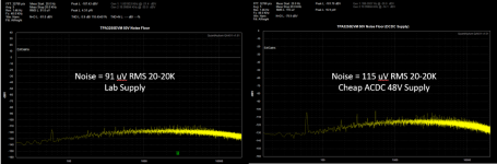
These are some follow-up measurements on the 3255 EVM that'd I'd previously posted in the "what's wrong with the 3255" thread.
Those measurements were made on a low-noise power supply. The first attachment here shows the comparison between a lab supply and a no-name 48V 480W power switching supply brick from Amazon (search DROK Adjustable DC Power Voltage Converter--it's good for a bit beyond 2x150W continuous into 4 ohms before limiting).
The summary is that whether lab supply or no-name switcher, the output noise is about the same. The lab supply is very close to TI's published spec. The no-name switcher isn't much worse.
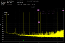
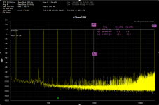
The next two plots look at multitone test. Multi-tone lets you look at freq response, crosstalk and THD is a single measurement. Note that into 8 ohms, you'll see at 20 KHz the output is about -0.9dB relative to 1K. Into 4 ohms, you'll see at 20 KHz the output is -2.3 dB relative to 1K.
These are tradeoffs that must be made in the design of the output filter on the EVM. No big deal, really, but be aware of you are aiming to drive 4 (or especially 2 ohm) ohm loads the rolloff at the top might be a bit more than you'd otherwise expect.
The M2 marker shows the crosstalk. This tone is generated at the amplitude of the other tones on the right channel (not shown) and by looking at the amplitude of this tone on the left channel, you can see the crosstalk, which is about -62 dB.
This amp continues to impress.
Those measurements were made on a low-noise power supply. The first attachment here shows the comparison between a lab supply and a no-name 48V 480W power switching supply brick from Amazon (search DROK Adjustable DC Power Voltage Converter--it's good for a bit beyond 2x150W continuous into 4 ohms before limiting).
The summary is that whether lab supply or no-name switcher, the output noise is about the same. The lab supply is very close to TI's published spec. The no-name switcher isn't much worse.
The next two plots look at multitone test. Multi-tone lets you look at freq response, crosstalk and THD is a single measurement. Note that into 8 ohms, you'll see at 20 KHz the output is about -0.9dB relative to 1K. Into 4 ohms, you'll see at 20 KHz the output is -2.3 dB relative to 1K.
These are tradeoffs that must be made in the design of the output filter on the EVM. No big deal, really, but be aware of you are aiming to drive 4 (or especially 2 ohm) ohm loads the rolloff at the top might be a bit more than you'd otherwise expect.
The M2 marker shows the crosstalk. This tone is generated at the amplitude of the other tones on the right channel (not shown) and by looking at the amplitude of this tone on the left channel, you can see the crosstalk, which is about -62 dB.
This amp continues to impress.
Attachments
- Home
- Amplifiers
- Class D
- TI TPA3255EVM