Thats the plan. When the Real one is finished, I will change the first clone to the real clone. ConfusedDo you plan to build a NS10 clone to compare with your real one?
 Me too
 Steen
What is a VOT? If I know already, I have forgottenif you can't afford VOT........
I am looking for a pair of 15" Tannoy Berkley's, they were earlier pretty popular around here.Steen
apassgear said:
The NS10 has about 1K output impedance and low power so it wont drive any headphone.
For this you would need to add a buffer to the output.
I don't have a ready solution for this, but will think about it.
If you only need is a headphone driver it will be best to tackle an amp that was specificaly design for this purpose, there are many projects on the forum you could try.
Hope you find a solution
Please excuse me Sir, why that 1K resistor at the ouptut elevating the output impedance?
Maybe removing it you could also drive a medium impedance headphone (something > 100 ohm)?
Moreover, what is the purpose of that LF351 ?
Is is a servo for offset nulling ? why with a cap at the output?
It seems that the original has an extremely good sound indeed:
http://forum.audiogon.com/cgi-bin/frr.pl?rprea&1129311740&read&3&4&
A good sound from a cap coupled preamp with a 317 based power supply ?
More blasfemous than "the Da Vinci code" indeed

By the way, is there a pcb for the clone ?
I am extremely interested in buying 3 samples, if not exaggerately expensive
Thank you very much for the extremely interesting 3D.
I understand it is a very good sounding SS line stage, my neverending dream !
Kind regards,
beppe
Hi Beppe.
NS10 was designed to be a lineamp to feed some 10K+ input amp and not a phone driver, you can do without the 1K resistor if you like but that won’t help the situation for 100 Ohm cans even with big caps at the output, to my knowledge. For this to work you will need a buffer that can deliver some power.
On the power supply you are free to do what you think it works better, Pi filters will do nice here too, try CLC or other more complex filters with or without regulation.
Regarding the opamp read the thread and you will find answers. It is biasing Q1.
As far as I know there was no PCB done other than a couple etched by our friend Steenoe.
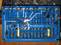
I will start populating the NS10-clone any time now. (I cant stay on that honeymoon with the A-X's forever ) I am looking forward to hear how it performes in comparison to the real thing.
For reference, this is the NS10:
http://www.diyaudio.com/forums/showthread.php?s=&threadid=92682&highlight=
Steen
) I am looking forward to hear how it performes in comparison to the real thing.For reference, this is the NS10:
http://www.diyaudio.com/forums/showthread.php?s=&threadid=92682&highlight=
Steen
apassgear said:Hi Beppe.
NS10 was designed to be a lineamp to feed some 10K+ input amp and not a phone driver, you can do without the 1K resistor if you like but that won’t help the situation for 100 Ohm cans even with big caps at the output, to my knowledge.
For this to work you will need a buffer that can deliver some power.
On the power supply you are free to do what you think it works better, Pi filters will do nice here too, try CLC or other more complex filters with or without regulation.
Regarding the opamp read the thread and you will find answers. It is biasing Q1.
As far as I know there was no PCB done other than a couple etched by our friend Steenoe.
Thank you very much indeed Sir, for your kind and valuable reply.
As you can well understand I am trying to learn something here.
Very interesting 3D indeed.
Thanks again and kind regards,
beppe
steenoe said:I will start populating the NS10-clone any time now.
(I cant stay on that honeymoon with the A-X's forever
I am looking forward to hear how it performes in comparison to the real thing.
For reference, this is the NS10:
http://www.diyaudio.com/forums/showthread.php?s=&threadid=92682&highlight=
Steen
Thank you very much indeed Mr Steen.
I will follow the evolution of your tests with the greatest interest.
I am always in search of a nice sounding line preamp in order to replace my present Bryston .4B (no soundstage reproduction.
I would like to write to you privately if I do not disturb.
Anyway great 3D indeed !
Sometimes I wonder if there is still something to discover.
This is maybe a 30 years old design that makes obsolete newer design ! Amazing !
Thanks again and my kindest regards,
beppe
M1 mc amp
Steen and others.
You have an M1 mc amp, simlar to the one I have obtained. Did you ever find a diagram for this unit ?
Somebody has been trying to fix a resistorproblem, but who ever it was couldn't find the correct resistor, and have tried to couple 2 different values to one. I can find out, that the resistor problem might be the only problem, so if you ore anybody in this forum has the scematics I would love to have a copy.
Which color is the + supply, black ore transparant ?

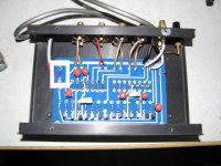
Here's a composite shot of the pcb with power connections.
-Mal
Attachments
No, I cant recall to have seen one. It should be fairly easy to draw one up, looking at the pcb. I can check out the value of the resistor you marked. I am a bit busy at the moment, but I will look at it as soon as I can.Did you ever find a diagram for this unit ?
Steen
Hi Malotron. Thats how I think it looks like. I will try to compare it to the pcb. Did you draw that up by hand? Nice schematic, thanks for posting.
The replaced resistor of E-type's, is the 10r going to ground at the power-inlet, I beleive. Which also answers the question of what color lead is positive and negative. (The negative is connected to the 10r resistor) I am a bit puzzled that they used 2 resistors to achieve 10r. If the purpose was to raise the wattage, you better check for shorts.
Steen
Did you draw that up by hand?
Naw, ExpressPCB(sch) and photoshop for the india ink on pub napkin look.

-Mal
Yes you may use any single opamp as long as its pin compatible to the one shown on the schematic.
For best results try to use an opamp with JFET at the imput like the LF351.
We would like to hear about your project, happy building and welcomed to the NS10 society!
P.D. will post the latest schematic (think I haven't done this) some changes were done that you should take in consideration.
For best results try to use an opamp with JFET at the imput like the LF351.
We would like to hear about your project, happy building and welcomed to the NS10 society!
P.D. will post the latest schematic (think I haven't done this) some changes were done that you should take in consideration.
Hello Apassgear,
thanks for the answer. I would like to build thie preamp as close to orginal as possible. Except....I will use dual supply for an op-amp. I was even able to get polycarbonate caps. For PSU, single one, I will use R-Core transformers ( one per channel ). I hope I have enough output voltage ( 19V what should give me 26.8V after rectification). Each transformer has has single secondary 19 V, 2Amps.
thanks for the answer. I would like to build thie preamp as close to orginal as possible. Except....I will use dual supply for an op-amp. I was even able to get polycarbonate caps. For PSU, single one, I will use R-Core transformers ( one per channel ). I hope I have enough output voltage ( 19V what should give me 26.8V after rectification). Each transformer has has single secondary 19 V, 2Amps.
19V on the secondaryseems somewhat low for a regulated supply giving 24/25 VDC.
The opamp should work from a single rail as Nelson did on the original and since you will have a rail at 25V no need for other two rails at 15V or so.
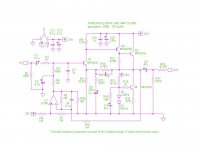
This is the last schematic...
The opamp should work from a single rail as Nelson did on the original and since you will have a rail at 25V no need for other two rails at 15V or so.
This is the last schematic...
Attachments
- Status
- This old topic is closed. If you want to reopen this topic, contact a moderator using the "Report Post" button.
- Home
- Amplifiers
- Pass Labs
- Threshold NS10 Lineamp PCB