I would be happy to curve trace one of those "winged" 6DQ5 oddities. I have conventional RCA 6DQ5 tubes and 21LG6A tubes here already to compare with on the curve tracer.
Although this cannot be deduced from the factory data, by static measurements the 6DQ5 tube behaves very similarly (or almost identically!) to the 6HF5 which was produced and presented much later. For the 6HF5 tube, I don't even have a built-in base on the NEUBERGER-RPM370 / 1 tube tester, but I made an adapter.
Are you sure that there's negative resistance in the Ig2 graphs? Yes, there are ups and downs, but these relate to the plate voltage, not to the screen grid voltage.
I'm not sure really. It does look suspicious but doesn't fit the rules for neg. R. I was having a hard time characterizing the neg. R after wg_ski mentioned it. The g2 current goes down with higher plate V, but virtually all pentode types have that curve property. But those are different electrodes.
The odd part of the curves is the screen current going down with lower plate V in a small region. Not exactly negative R. However plate current could go up (and so plate V go down) if the screen current dropped (and increased the screen V). Sort of an indirect neg. R. I guess one would need to experiment some to see if there really is an issue there.
-----------------------------------
I have some 6P41S tubes in my small box of 4P1L tubes, I don't even remember ordering them. Maybe they came with the 4P1L.
I also have a GU50 tube. Wavebourn sent me a couple years ago. One has since gone "white getter". I did post some curves for them quite a while back. Including fixing the knees (squareness) with some +LV on grid 3.
And some 6F12P high gm pent. + triode. Wavebourn and others have been using these for a front end and splitter.
-------------------------------------
6HF5 is identical with 6JS6, and both are quite close to the 6LG6. 6JE6 is close too.
Here are the GU50 curves from way back:
https://www.diyaudio.com/forums/tubes-valves/160240-suppresor-grid-feedback-7.html#post2086436
I could run those again (assuming my last tube is good still) with the scale units. (most likely 50V/div Horiz., not sure what was set for vertical I or grid V steps unless the previous post had them listed)
OH, here is the earlier post on the GU50 with units included:
https://www.diyaudio.com/forums/tubes-valves/160240-suppresor-grid-feedback-4.html#post2071698
And here are some curves for 4P1L with different +V on grid 3 for squaring up the curves.
https://www.diyaudio.com/forums/tub...le-practical-tube-analyzer-3.html#post6069871
I guess I’ll just have to see how much trouble it gives me. If it turns out not to give me any more headache than regular audio beam pentodes do, then I won’t worry about it. I’ve fought little “snivets” before, and the usual global loop frequency compensation methods have always fixed them. Since I don’t have spice models I can only estimate where the high frequency poles are from the various time constants - and when you can measure the frequency of oscillation you can get a better estimate and fix it. Low frequency oscillations have been more troublesome - either the output transformer can handle global feedback or it can’t. One reason I’m sticking with Hammond output iron - low end seems to be much better than random stuff I’ve found and tried to build with. Can’t really just do ultra linear with sweep tubes and 43% taps so feedback becomes essential.
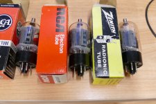
I have ~ 80 or maybe more 6DQ5 from American manufacturers (RCA, Sylvania, DuMont, Philco, GE, etc.), and some ~ 30 of them are from RCA. Only 3 have these extra wings in RCA tubes. I do not have a "Curve tracer" but only a NEUBERGER-RPM370 / 1 tube meter on which I can statically measure the tubes and, if we so agree, send one or more of them to you.
Keep in mind that US makers built tubes for each other, so in many cases the brand name on the tube does not mean that it was made by them. All of the RCA 6DQ5's in the pictures from post #1354 with the getter flash at the top of the tube are made by Sylvania. The two clear tops are actually RCA's.
In most cases the maker can be identified by the type number. If the number is screened inside an octagon it's an RCA built tube. If it is screened on with the letters USA (no periods) underneath its a Sylvania built tube. If the type number is screened on with U.S.A. (with periods) and some date coding dots underneath it's a GE built tube.
Many Sylvania built sweep tubes started getting the little winglets added late in the production run. All of my Sylvania 36LW6's have them, but only some 6LW6's have them GE went through several different fin designs on their big sweep tubes ranging from huge to none.
Zenith and most equipment manufacturers bought tubes from whoever gave them the best deal at the time. Most of the Zenith tubes that I have are GE made.
The presence of a dot pattern below the type number and possibly "EIA 185-_" where the number after 185 could be anything, would confirm a GE tube. GE tubes made before 1952 did not have the dots. U.S.A. was not always present before 1960.
185 is GE's EIA registration number, but I have seen it used on GE branded tubes that were made by someone else, or left off entirely. The EIA number is a clue, but not a guarantee as to who made an electronics component. RCA's EIA number was 274, and Sylvania was 312.
Post a picture showing the plate structure, and another showing the detail of the type number lettering, so we can tell what you have. .
Those are made by RCA. Unfortunately they have the same design flaw that I have found in many RCA sweep tubes that use the same plate like the 6AV5GA.
Notice two slots cut in the plate where the fin meets the plate box. This is the point in the box where the beam plates concentrate the beam and the fins are there to conduct the heat away from the hot spot so it can be radiated out of the tube. The slots block that transfer. Later vintage RCA's lost the slots.
These tube are fine at their rated dissipation level, but can not be abused like the GE's and Sylvanias can.
The picture shows two RCA 6DQ6B's and a GE made Zenith. The rounded corners on the plates with two small holes are indicative of GE's common corporate plates that went into all of their later sweep tubes. All were the same except for the height.
The box plates with square holes were most often seen in RCA and some Japanese tubes.
Box plates with no holes were common in Sylvanias.
Attachments
In any TV sweep tube the average plate current, peak plate current, and all screen grid ratings should be respected. The plate dissipation rating has some "wiggle room" when used in an audio amp, especially a push pull amp.
The horizontal sweep circuit in a TV set runs at full power all of the time. A ramp voltage drives the tube from cutoff to full conduction, then shuts completely off for a few mS and ramps back up again....forever. Exceeding the average current overheats the cathode shortening it's life. Exceeding the peak cathode current can lead to a tube arc, possibly blowing the tube and other parts.
The horizontal output tube was the most common failure item in a TV set, so the tube manufacturers kept improving them, so it was common to see plates much bigger than the ratings suggest. Compare the plate in an 18 watt TV sweep tube to the plate in an 18 watt audio tube. Any TV sweep tube made after the mid 50's will have a bigger plate than a similar rated audio tube, so some extra headroom is available.
A single ended audio amp runs at maximum dissipation at idle, so like the TV sweep tube there is some headroom due to the bigger plate, but not as much as in a push pull application where the average dissipation is far less than the peak dissipation. Many TV sweep tubes don't fare well in a SE audio application since they are often not linear enough in the range of current needed for continuous class A operation.
Much of my experimentation involved 6AV6GA's which are older than the 6DQ6 types, but often contained the same plate structure in the later production years. I can't find the page on this forum where I tested all the different plate structures in the 6AV5GA's, but the RCA's with the slot in the plates were the least capable of use in class A SE.
GE rates their 6DQ6B at 18 watts of plate dissipation. I don't have the RCA data handy, but I seem to remember 15 watts. I know that the GE's will work fine at about 25 watts of plate dissipation. I have tested them to 100 watts per channel of audio power in push pull with no issues. I have not tested any RCA's in an audio amp.
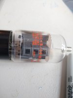
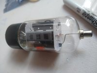
I was getting set to do some curve tracing of the 6P41S and 25HX5 tubes this morning and usually I can just look inside the bottom of the tube to determine which pins are what for connecting up to the tracer.
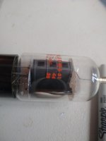
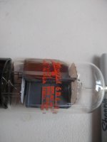
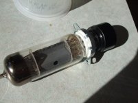
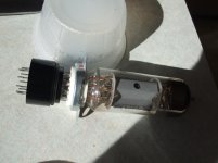
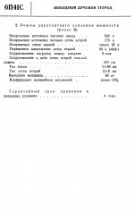
But the 6P41S has some unusual strapping between the pins and electrodes. Small islets are stamped thru the mica where grid 1 and 2 pin wires and electrode strapping are joined. Not too out of the ordinary until you notice the islets go -thru- the mica and are right below the corners of the plate on all four corners of the plate. Less than 1/32" gap between them and the sharp plate edge. I can't read the Russian datasheet, but looks like 400V max for the plate. If the mica is a little off position that could be more like 50V Max. The gap on the other side of the plate (not shown) is even closer than the pictured one.
But the 6P41S has some unusual strapping between the pins and electrodes. Small islets are stamped thru the mica where grid 1 and 2 pin wires and electrode strapping are joined. Not too out of the ordinary until you notice the islets go -thru- the mica and are right below the corners of the plate on all four corners of the plate. Less than 1/32" gap between them and the sharp plate edge. I can't read the Russian datasheet, but looks like 400V max for the plate. If the mica is a little off position that could be more like 50V Max. The gap on the other side of the plate (not shown) is even closer than the pictured one.
Attachments
Last edited:
Geez, 190V, and some Ebay sellers are calling it a replacement for 7868 tubes! (550V)
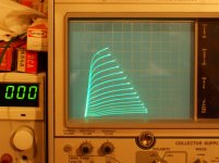
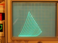
I got some curve tracer pics in of the 6P41S just before the batteries went out on the camera. I'll be off to the grocery store later and pick up some new batteries. D--- camera eats batteries.
a) 6P41S in pentode, 50V/div Horiz., 50mA/div Vert., -2V steps, 170V on grid2
b) 6P41S in triode (grid2 directly to plate here) 50V/div Horiz., 50 mA/div Vert., -4V steps
Attachments
...But the 6P41S has some unusual strapping between the pins and electrodes. Small islets are stamped thru the mica where grid 1 and 2 pin wires and electrode strapping are joined. Not too out of the ordinary until you notice the islets go -thru- the mica and are right below the corners of the plate on all four corners of the plate. Less than 1/32" gap between them and the sharp plate edge. I can't read the Russian datasheet, but looks like 400V max for the plate. If the mica is a little off position that could be more like 50V Max. The gap on the other side of the plate (not shown) is even closer than the pictured one.
The maximum anode voltage for 6P41 is Ua = 500V, although I tested it up to a voltage of Ua 700V without any problems.
Attachments
- Home
- Amplifiers
- Tubes / Valves
- Those Magnificent Television Tubes