...Want to run 750 volts in triode? ...
EL51 work reliable and stable at 750V in triode circuit.
Attachments
I assume that your amp is the sound application PP, if so may I ask what the OPT and the idle currents are?
My amp is an SE amp of my own design, the Tubelab SSE. I have explored the upper limits of SSE power output using a bunch of "previously auditioned" Electro Harmonix KT88's I got cheap about 10 years ago. I wired the amp up to a variable power supply and kept cranking up the B+ voltage until I felt that something bad was about to happen. I then backed up a bit and found a suitable power transformer. I have one SSE amp that runs a B+ that is around 465 volts, but since the amp is cathode biased, there it about 425 volts across the tube. Running in UL I set the cathode current at about 100mA to get the best bass with the OPT on the 3K ohm tap. This is usually only done when I play some loud dynamic music. Most other music sees triode mode with about 75 mA of current and the OPT on the 6K ohm tap.
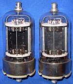
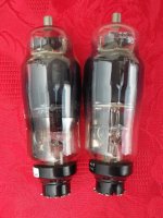
Here are some pics of mica insulators for TV Sweep tubes.
I'm sure that the mica can provide a leakage path inside the tube from G2 to G1. So can "gas," the less that perfect vacuum that's found in most modern new production tubes, and a fair percentage of the 50+ year old tubes we play with.
Even in a box on a shelf, the vacuum inside will eventually collect a minute amount of contaminants from air leakage, and the imperfect nature of the internal components. Then we crank them up and make them hot, adding to the cloud of "gas" inside. A voltage potential between two metal elements in a gaseous environment of less that atmospheric pressure will cause some of the "gas" to be ionized in a manner similar to a neon light. Then there will be an unwanted path for current to flow.
As stated some of this will be from G2 to G1 since they are very close together. This current will cause the voltage on G1 to be pulled in a positive direction cancelling out some of the negative bias, causing tube current to increase, generating more heat. More heat, more ions, more unwanted current.......runaway happens.
This is why the tube makers publish a "maximum grid circuit resistance" spec. The lower the grid circuit resistance, the lower the change (in the positive direction) in grid voltage caused by the unwanted current paths (mica and vacuum contamination). This spec is often ignored, or purposely violated in the quest for more gain (especially in guitar amps) and is the main reason for random tube meltdowns in an otherwise good working amp.
Both of the contamination mechanisms cause accumulation over time, so that shiny new pair of new production Tung Sol KT88's may be fine for the first year or two, then randomly go bang down the road. Particularly if run hot. So if you are going to lean on a tube in an amp design, keep the grid circuit resistance down. A mosfet driver is excellent here for grid voltage control, since the voltage can not creep up.
I'm not familiar with the EL51 since they are rather uncommon here. The 7403 is the Bendix version of the 3D21WB (not 3D21A or 3D21WA) which used to be relatively common in military surplus. Unfortunately many of the surplus tubes are gassy and will runaway.
Last edited:
Want to run 750 volts in triode? Use 7403's....If you can find any. Check out the triode curves on these guys. They sound real nice too.
i knew those curves were familiar
http://rtellason.com/tubedata/3D21WB.pdf

All my 6HJ5 experiments / amps were push pull. The bias current depends on the plate voltage. The big powered amps ran 600 volts and I set the idle current at about 30 mA. This runs the tubes at 18 watts idle dissipation, which is OK for a 24 watt sweep tube, but I wouldn't go much higher.
The distortion at 100 milliwatts is primarily crossover, which drops to a minimum above 25 mA or so in the mildly modified Pete Millett design. I added a few mA for good measure. I did run a test at 650 volts and 25 mA using my HP variable power supply. Nothing bad happened, but I had two different low $$$ ways of getting 600 volts, so that's where I stopped.
The lower voltage testing ran a bit more current, maybe 35 mA for a 450 volt amp. I never built any......why build wimpy amps when the 100+ watt version cost the same $$$$
I am not particurly after maximum power, as odd as that may sound.Looking for more ClassA with a transition to AB. Perhaps my thinking is wrong here. 10-12W class A and around 20w total would be lovely. Been playing with load lines seeing what I could come up with, hence the question of bias. Thanks for the reply. I'll start a new thread for the build as I get things drawn up and planned out. Corrections and advice welcome.
7403/3D21WB and EL51 appear to have ceramic supports, rather than mica. Different ballpark.
Now if they were only $4....
i had a chance to use a pair, and indeed they sounded very good, but luck had
it and one tube gassed out, i have to abandon it...
I am not particurly after maximum power, as odd as that may sound.Looking for more ClassA with a transition to AB. Perhaps my thinking is wrong here. 10-12W class A and around 20w total would be lovely. Been playing with load lines seeing what I could come up with, hence the question of bias. Thanks for the reply. I'll start a new thread for the build as I get things drawn up and planned out. Corrections and advice welcome.
someone posted a pp el509 with had an output of 80 wats at a B+ of just around 300+ volts maybe a couple of years back.......
I never checked, but I bet that 125 WPC amp that ran on 650 volts was still in class A at 10 watts. Either way, you could probably get a bit further while staying in class A by reducing the voltage and running a bit more current.
Most big color TV sets ran the horizontal sweep tube at 300 to 400 volts DC. The average plate voltage considering the sawtooth waveform on the plate is probably 200 volts or so. Maximum average cathode current spec is 280 mA. I would still try to find a spot that kept the dissipation around 18 to 20 watts.
The sweep tube in a TV set doesn't run in class A, but it runs full tilt all the time. there is no volume control on the CRT scanning circuit, and most color TV's used a shunt regulator on the 25KV supply derived from the horizontal sweep, so the total current was rather constant. Many TV's ran the horizontal sweep tube hard......that's why they were the highest failure part in the TV.
 OT posts moved to the safety practice thread, working with tube is fraught will shock hazards....anyone working on tubes know this....
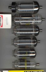
From looking at pics on Ebay, looks like the tested "Raytheon" 40KG6/PL509 was manufactured by Matsushita in Japan. And darn, the place (on Ebay) where I bought it, has doubled the price now on the other one! No P-P amp for those now. Can't get the Chinese sub-mini plate caps to stay on them anyway. Another odd thing about this tube is it does not have a evacuation stem seal. (not even the bottom) An advanced manufacturing process apparently.
Last edited:
I'm afraid that by the time I needed a replacement tube, I would need to get credit references. I always buy enough quantity of any interesting tube so I won't have to buy them again, and that's out of the question for these tubes. I sure feel sorry for anyone who has an OTL using PL509s.
I suppose one could look into the Russian 6P45S variant, but they're almost as expensive. I'm not too thrilled by sub-mini plate caps and Magnoval bases in any case.
I suppose one could look into the Russian 6P45S variant, but they're almost as expensive. I'm not too thrilled by sub-mini plate caps and Magnoval bases in any case.
Last edited:
Sadly very few interesting tubes in UK . I did think of importing a selection from USA but I think I waited to long. But I'm at least 3 years behind schedule on my existing projects so would be 2020 before I would even work out what I was thinking of doing with them. And a pair of 509s with the right Iron will do 100W reliably so fhere are several scenarios where value for money isn't that bad. If you have a box of dollar specials already, then its a different set of trade offs .
And at least they are still in production, albeit at a price and without the end caps. Dunno how good a copy the JJ's are tho.
. I did think of importing a selection from USA but I think I waited to long. But I'm at least 3 years behind schedule on my existing projects so would be 2020 before I would even work out what I was thinking of doing with them. And a pair of 509s with the right Iron will do 100W reliably so fhere are several scenarios where value for money isn't that bad. If you have a box of dollar specials already, then its a different set of trade offs .And at least they are still in production, albeit at a price and without the end caps. Dunno how good a copy the JJ's are tho.
Bill, we do have plenty of pl36 here (if you don't mind the heater voltage) which are likely pretty similar to 6cb5. The datasheet has g2 curves (and they look pretty good) which are a good place to start. What we really lack, here in the UK, is a source of reasonably priced output transformers. Sowter are great but fairly pricey. I recently found, to my dismay, that my cupboard was bare of PP transformers. I have been planning to try Smoking-amp's crazy drive, but this lack of iron has held me up. I will probably initially try the crazy drive as a driver stage for Mosfet source follower outputs.
I have some of these Matsushitas. I have disasembled one dud some time ago and if I find it I take some photos of the internals.Some TV Sweep tube pics, with the 40KG6/PL519 for comparison.
From bottom to top: 21LG6A, 6HJ5, 35LR6, 26LX6, 40KG6, 36LW6
In my PL509 collection the Philips PL509's have stronger gain and emission, but Matsushitas are equally reliable and stable.
- Home
- Amplifiers
- Tubes / Valves
- Those Magnificent Television Tubes