Peter Daniel said:No problem. I don't know if it's because of thickness, but it seems to be sounding sustantially better than previous version which had only 1/2" panels..")
Then just imagine how much better TWO INCHES would sound! C'mon, Peter, don't be half-assed about this. I got bills to pay.
se
Peter Daniel said:No problem. I don't know if it's because of thickness, but it seems to be sounding sustantially better than previous version which had only 1/2" panels..
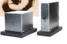
Looks great! How did you mill out the back panel? It looks much more professionally done then the first one.
Also, is that a Noble 50k pot?
--
Brian
Peter,
In your tight P2P wiring do you use any special trick to keep your layout uniform or is it just practice? I can get mine fairly tight but not nearly as tight as yours and the components tend to flop around a little during the soldering and don't maintain a neat uniform appearance between channels. Aligator clips work in some cases but not enough to make a difference. Any pointers?
In your tight P2P wiring do you use any special trick to keep your layout uniform or is it just practice? I can get mine fairly tight but not nearly as tight as yours and the components tend to flop around a little during the soldering and don't maintain a neat uniform appearance between channels. Aligator clips work in some cases but not enough to make a difference. Any pointers?
Very compact, nice Peter!
But are potmeters not very impractical for dual mono ? Why don't you use stepped att. ?
BTW: are your BG's larger than the ones on the 47 labs picture. Jean-Paul had bought some 1000 uF BG's that were very large, diameter larger than the width of the opamp!
Fedde
But are potmeters not very impractical for dual mono ? Why don't you use stepped att. ?
BTW: are your BG's larger than the ones on the 47 labs picture. Jean-Paul had bought some 1000 uF BG's that were very large, diameter larger than the width of the opamp!
Fedde
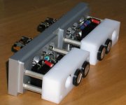
Peter,
I was reading one of the Gain Card reviews, and the reviewer
mentioned that the GC is so small that some large speaker cables
could make connections cumbersome. Since the GC isn't big and
heavy the cables could tend to drag them around. So i guess
adding mass to your amps could be good from a practical point
too. I would imagine that your amps weigh more than the
Gain Card does?
Has anyone looked in to cloning the integrated amp? I think
it's a lot cooler looking than the GC.
((Peter needs another project, right?!!))
m.
Attachments
Those BG are 22 x 36mm. I wouldn't be so sure that 47 Labs using BG, they take the jacket off for a reason, right?
The panels are done by machine shop now and are polished at the same place as Sonic Frontiers and Bryston are done.
When I do p2p are always go with a simplest and shortest connection (and this can be done only one way) so it's always uniform. I never use aligator clips, just my fingers, tweezer and small scredriver. The solder diepenser usually end ups in my mouth.
I'm not using switching pot, since it's more complicated, bigger (woudn't match that design) and more expensive. I found out that a pot can sound pretty good too, the one I'm using is dented so stereo adjustment is easy. I also match them, so tracking is very good. It may actually sound better than switched one with average resistors. And it's Nobel.
Matttcattt said:... could someone please explain the classes or point me to a document that does?
As explained by another person:
"For convenience, engineers usually characterize amplifiers by circuit topology, the type of active components they use, load type, and even operating voltage: CLASS A, B, C, D, etc. Circuit topology describes how current is "steered," or controlled, within a power amplifier before it is delivered to a speaker load.
Class A is the simplest, most basic topology. Reproduction of music requires speaker motion both in and out. To do this, amplifiers must "source and sink" current. In a Class A amp only one direction of current control is used. To generate both directions of output flow, a constant current stage is subtracted from a variable current stage.
Pros: Since neither output stage ever turns off, device non-linearity and turn-on/turn-off time can be minimized or ignored, resulting in very low distortion designs.
Cons: As the maximum output is limited to the constant current stage, at idle this stage must put out full power and the variable stage must absorb this full power. Transformer, heat sink, and output stage must be sized for continuous duty at maximum power. Because of cost and the amount of waste heat generated by this approach, Class A only appeals to esoteric hi-fi designers, where lack of efficiency or price is no object.
Class B topology uses two variable output stages, one to source current and the other to sink current.
Pros: This topology overcomes the poor efficiency of pure Class A designs, only delivering power as needed. Transformer and heatsinks can be sized to match typical demands of music being reproduced.
Cons: Both output stages turn completely off, then on again, during each cycle of a waveform. Time delay and low-level non-linearities cause severe distortion, called "crossover distortion," during transition from source to sink output stages. This type of distortion is worst at low output levels. Pure Class B is only used in the lowest-cost, lowest-fidelity designs.
Class A/B topology, as you may have guessed, is a combination of Class A and Class B. Using two variable output stages like Class B but keeping them from ever completely turning off, you get near Class B efficiency with near Class A's low-distortion performance.
Class C topology combines active devices with resonant magnetic components for high efficiency at radio frequencies. This topology is not used in audio-frequency designs.
Class D topology uses source and sink output stages that consist of full-on or full-off switches. These output stages toggle from full sink to full source at a rate significantly higher than the highest audio frequency to be reproduced. The ratio of time sinking to time sourcing controls the audio output, with a 50% ratio delivering zero output.
Pros: Class D offers significantly higher efficiency than even Class B, which at 1/3 power is wasting more power inside the amplifier than it delivers to the load. Losses in Class D designs are limited to turn-on time of the switching devices and resistive losses in these devices and output filtering.
Cons: Class D amps require more complex circuit designs with extensive shielding and filtering.
Class G & Class H topologies are variations on Class B that use multiple source and sink output stages. Low-level signals are handled by one pair of output stages, while higher-level signals are handled by other pairs. Each pair is optimized for the power range it delivers.
Pros: More efficient amplifiers can deliver the same output power with smaller transformers and less heat sink.
Cons: Circuit complexity increases, which adds cost. Switching distortion similar to Class B's crossover distortion occurs at each output level transition."
Peter Daniel said:Those BG are 22 x 36mm. I wouldn't be so sure that 47 Labs using BG, they take the jacket off for a reason, right?
Hmmm, good point. It wouldn't surprise me if they found a budget solution there too
I'm not using switching pot, since it's more complicated, bigger (woudn't match that design) and more expensive. I found out that a pot can sound pretty good too, the one I'm using is dented so stereo adjustment is easy. I also match them, so tracking is very good. It may actually sound better than switched one with average resistors. And it's Nobel.
Ah dented pots, nice. I didn't know they existed.
BTW: I am trying to find your post about the resistors values for a 4 deck 23 step switch. Spend 20 min and could not find
Could you please repost this??? (I already have a 23 step switch, will do the job!)Fedde
You have to know which words to use for search. >Ladder shunt attenuator< worked for me. http://www.diyaudio.com/forums/showthread.php?s=&postid=129109#post129109
>Ladder shunt attenuator< worked for me. http://www.diyaudio.com/forums/showthread.php?s=&postid=129109#post129109Steve Eddy said:
Great! My Alcoa stock just went up 10 points! Thanks, Peter!
se


LOL
Steve Eddy said:
Then just imagine how much better TWO INCHES would sound! C'mon, Peter, don't be half-assed about this. I got bills to pay.
se
I need 1/4" notch for mounting purpose. It leaves 1/2" on the outside. 1/4" would be a minimum for good looks, but when you are facing $3 price premium for extra material why not go for better look (and feel) of half inch?
Two inches are not practical.
Peter Daniel said:You have to know which words to use for search.
The problem was that I tried to find the info in this 60+ pages of clone mess
Should have looked in the other thread...
Muchos gracias,
Fedde
Peter Daniel said:I need 1/4" notch for mounting purpose. It leaves 1/2" on the outside. 1/4" would be a minimum for good looks, but when you are facing $3 price premium for extra material why not go for better look (and feel) of half inch?
Two inches are not practical.
I think my Alcoa stock going up a few more points is quite practical.
se

Peter Daniel said:You keep bugging me about it and I'll start working with acrylic.
Hang on, lemme see what DuPont stock's going for...
se
- Status
- This old topic is closed. If you want to reopen this topic, contact a moderator using the "Report Post" button.
- Home
- Amplifiers
- Chip Amps
- This is not just another gainclone