dhengkoel said:Dear all;
I found this nOrh Le Amp Monobloc Amplifiers picture from http://www.tnt-audio.com/ampli/norhleamp_e.html ....
regards:
ragil.hastomo
nOrh..you too!?!
 And for only US$ 295.00?
An externally hosted image should be here but it was not working when we last tested it.
argo
Tried one channel yesterday of the gainclone. I seem to get almost 100mV DC at output without any input connected.Also there is a low and just perceptible buzz/hum from the listening position that sounds like AC ripple.
With input connected sound seems quite satisfactory as far as I can tell with one channel.
I am not using any caps at all, (apart from PS), so I guess it could be the source of the problems but why am I getting such a high offset with no input?Is it a matter of matching the 220k resistors? I am using the second 220k to connect inverting input to ground.
Hi,
The Amp is most likely oscillating. The circuit I originally proposed relies on the Volume control AND the input to ensure stability. This is not the most ideal solution as some have discovered with regards to reliability.
Hence I would now suggest to have a resistor of 10k Value on the non-inverting input of the Amp, no capacitor and a 22k Resistor to ground on inverting input. This way the Amplifier will not oscillate even with no volume control and no source connected.
Another issue in your case is the missing input coupling cap. This will cause offset, much depending upon the rest of the circuit resistances.
Sayonara
Tried one channel yesterday of the gainclone. I seem to get almost 100mV DC at output without any input connected.Also there is a low and just perceptible buzz/hum from the listening position that sounds like AC ripple.
The Amp is most likely oscillating. The circuit I originally proposed relies on the Volume control AND the input to ensure stability. This is not the most ideal solution as some have discovered with regards to reliability.
Hence I would now suggest to have a resistor of 10k Value on the non-inverting input of the Amp, no capacitor and a 22k Resistor to ground on inverting input. This way the Amplifier will not oscillate even with no volume control and no source connected.
Another issue in your case is the missing input coupling cap. This will cause offset, much depending upon the rest of the circuit resistances.
Sayonara
Kuei Yang Wang said:
The Amp is most likely oscillating. The circuit I originally proposed relies on the Volume control AND the input to ensure stability. This is not the most ideal solution as some have discovered with regards to reliability.
Hence I would now suggest to have a resistor of 10k Value on the non-inverting input of the Amp, no capacitor and a 22k Resistor to ground on inverting input. This way the Amplifier will not oscillate even with no volume control and no source connected.
I am not sure whether you are discussing the gainclone or the inverted gainclone. Nonetheless, the gainclone circuit will certainly benefit by having a DC bias path, i.e. resistor, to ground at the non-inverting input. This should improve stability and DC offset at the output.
As for the inverting gainclone (with the 220k resistor from the non-inverting input to ground), I think it should instead have a 10k resistor to ground (actually 10k||220k), since the idea is to match the inverting input's impedence at the non-inverting input. This is going to involve some tradeoff between offset current and offset voltage, but the power supply rejection may be improved.
Building, testing, and tweaking as soon as the parts show up,
Jeremy
ok so you used the shematic on this page, without the blue resistor. Each other value is keptPeter Daniel said:The schematic is at the top of this page. I didn't try the resistor yet, but I will.
wich chip did you use?
what ps?
K.Y.W
I am bit confused with your schematics which you kindly posted.
I don't see any connection between the 220k feedback and 22k to groung with any input.
My gc has the 10k input on + and a 220k from - to gnd.Why would changing it to 22k help?
I understand oscillations make the chip quite hot but mine runs cool.I also have output caps on my pre so I omitted the input caps.
Here is my set up so you know the connections:
Attachments
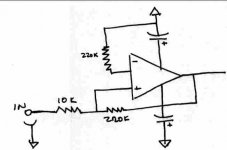
protos said:K.Y.W
I am bit confused with your schematics which you kindly posted.
I don't see any connection between the 220k feedback and 22k to groung with any input.
My gc has the 10k input on + and a 220k from - to gnd.Why would changing it to 22k help?
I understand oscillations make the chip quite hot but mine runs cool.I also have output caps on my pre so I omitted the input caps.
Here is my set up so you know the connections:
protos,
If this really is your schematic, I am pretty sure you don't have an amplifier. Switch the +/- symbols on the op-amp, and you will have an amplifier.
Jeremy
Bricolo said:ok so you used the shematic on this page, without the blue resistor. Each other value is kept
wich chip did you use?
what ps?
I used 3875 chip and 2 x 24V, 400VA transformer.
Hi,
Okay, in that case things should be okay. The KEY issue is with the input UNCONNECTED. In that case the amplifier will be instable. If an amplifier that should be quiet hums this is often a sign that it oscillates, gainclones should be DEAD quiet.
To "cure" the "open input" issue I suggest you place a 22k resistor to ground on the INVERTING INPUT. This way, no matter what external impedances and connections are present the Amp always operates with a noisegain of 11 and will be stable. Then simply make the resistance/impedance on the non-inverting input match, 10k - 15k should be close enough.
You may wish to try this and see what happens.
Sayonara
I understand oscillations make the chip quite hot but mine runs cool.I also have output caps on my pre so I omitted the input caps.
Here is my set up so you know the connections:
Okay, in that case things should be okay. The KEY issue is with the input UNCONNECTED. In that case the amplifier will be instable. If an amplifier that should be quiet hums this is often a sign that it oscillates, gainclones should be DEAD quiet.
To "cure" the "open input" issue I suggest you place a 22k resistor to ground on the INVERTING INPUT. This way, no matter what external impedances and connections are present the Amp always operates with a noisegain of 11 and will be stable. Then simply make the resistance/impedance on the non-inverting input match, 10k - 15k should be close enough.
You may wish to try this and see what happens.
Sayonara
Hi everybody !
Anyone has ever tried a 2 X 30 Volts power tranformer for the Gainclone ?
Would it be too much ? What are your impressions ?
Also, when working on another amp, I have remarked that the voltage increase slightly when connecting a load to it. Is there any way to calculate this phenomenon ? (or at least approximate it)
Thanks !
Elkaid said:Hi everybody !
Anyone has ever tried a 2 X 30 Volts power tranformer for the Gainclone ?
Would it be too much ? What are your impressions ?
Also, when working on another amp, I have remarked that the voltage increase slightly when connecting a load to it. Is there any way to calculate this phenomenon ? (or at least approximate it)
Thanks !
im going to try, i dont really have a choice as i have two spare 300va 30v transformers lying around - it should just work as the maximum voltage is 42v
")
noise gain resistor
Kuei Yang Wang is correct about the 22k resistor to ground. I proposed this same "trick" on another gainclone thread. It's really an old opamp "trick" for assuring stability in the inverting mode when desired signal gain is less than minimum gain for amplifier stability.
In this situation, the term "noisegain" simply refers to gain increase of the noise component not the signal component. The minute increase in noise will not be noticeable, and will make the amp stable, cool running and better sounding.
With my inverted version. I used a high quality input coupling cap and jumpered it in and out with a very short silver wire (2.5") and could only hear an imperceptable difference in quality on one side, but on the other side I think I got a bad cap as I get a buzz with it in and it gets louder when I give the cap a squeeze. Check your components, you might have a funky resistor or a questionable solder joint.
- Status
- This old topic is closed. If you want to reopen this topic, contact a moderator using the "Report Post" button.
- Home
- Amplifiers
- Chip Amps
- This is not just another gainclone