I think I've seen terminal strips, similar to the screw down type, but with push down springed buttons. Those would be ideal, quick AND insulated.
Well, there certainly ARE individual spring terminals for speaker connects. But those would most likely be quite pricey and maybe only one wire capable.
Another way would be to use Banana Jacks with stack-able wire plugs.
Well, there certainly ARE individual spring terminals for speaker connects. But those would most likely be quite pricey and maybe only one wire capable.
Another way would be to use Banana Jacks with stack-able wire plugs.
Last edited:
I ordered a bag of them on Ebay last night.Yep, multiple wires fit into a long strip-like hole. Just push down the spring to insert wires, then release. A fairly stiff spring. "Vector T30" will bring up bags of them on Ebay. Unfortunately they're NOT insulated. Kind of a mouse trap for wandering fingers, arrayed out on those sockets.
All of my previous tube labs were 400 volt (or more) finger traps. I learned long ago to use a "two step" process to insure a dead board before fingers get near it. #1, turn the power supply output off. #2 pull out the banana cable that connects the power supply to the board. For line powered experiments, pull the plug out of the wall outlet, and remove the other end of the cord from the IEC jack on your project. Just yanking the cord from the wall isn't good enough when the cord on your soldering iron looks just like the one on your live project! Another lesson learned, put some heat shrink or even tape around the dual banana plug that feeds your project. Sooner or later you may need to kill power in a big hurry, and often the easiest way to do that is to yank the dual banana out of the power supply. When you put the wires into the plug you stuck them through the holes and tightened the screws. Those little stubs sticking out the other side are LIVE and in the right spot to blow a little hole in your fingertip when the knob on the supply is all the way up. Yeah, that got me to fix the broken "operate / standby" switch on the supply.
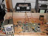
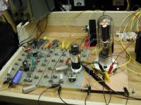
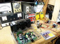
I have made and discarded several prototyping systems. Here are a couple pictures of Tubelab II from 2003 or 2004. This is the very beginning of the original Tubelab TSE board. The IXYS 10M45 chip did not exist, and PowerDrive was not even yet a dream. I was testing dozens of driver tubes in the bottom socket with a pentode CCS load in the top socket. The pentode was likely a 12GN7. The output tube was a 45. I still have the rest of the Fahnestock clips used to build these boards in their original bag from Mouser. The stock number is now dead, but similar clips are still on Amazon.
Within a few months I had discovered the 5842, the Constant Current Diode that replaced the pentode CCS, and the brand new 10M45 CCS chip that replaced the Constant Current diode, and Power Drive. Two small glass diodes can be seen in clips on the right side of the driver board. The 10M45 and a mosfet source follower buffer form the PowerDrive circuit that loads the 45 and feeds the 845. They are mounted on the heat sink back behind the 845 tube.
In this iteration of the tube lab each "PC board" all modules were made with blank G-10, no copper. There is a Fahnestock clip for each pin on the tube socket, and several unconnected clips. The modules are rather large and somewhat clumsy to use. Building a multi stage guitar amp on this system would not be possible. The system seen in post #33 is more generic, anything can be built as there are just tube socket modules, and empty generic modules. There were a couple purpose built Power Drive style modules and a module with a row of pots and switches. It's building style was also clumsy, created more wiring, and took longer to change individual parts due to the screw terminals.
I plan to reuse the white plastic base from Tubelab III. It is actually built on the wood base from Tubelab II. Tubelab II had a hinged lid that never got used since it wouldn't close with anything larger than a 6V6GT installed. I cut the sides off when I put the white plastic on. The copper screen is still in place and connected to circuit ground. It cuts down on noise and stage to stage coupling from all the wires.
For now, the individual modules will be single stage amps with all of the major components easily swappable without a soldering iron. They will be PC boards, each 100 mm X 100 mm or smaller, and JEDEC base specific like those from Tubelab III. I will try the T30 thingies, and if they don't work out, I have lots of the spring thingies from Maker Trading Post.
I think these would have been useful if a swappable part mechanism could be added, but they are no longer available either. It seems that there isn't much demand for real circuit tinkering any more. It's just too easy to copy something......until there is nothing cool left to copy.
https://www.diyaudio.com/community/threads/valve-wizard-experimental-pcbs.408565/
https://valvewizard.co.uk/universalpcbs.html
Attachments

Tektronix had some diode test clips for their curve tracers that are interesting. They're hideously expensive on Ebay in this form, but if the actual metal component clips (or similar) were available (like a bag of them) they might be quite useful. You could just lay out the basic circuit on a PC board and then drop components in all day.
Well, worst case, could solder in the ends of clip leads to the board, little short stubs to clip the components into. I guess some alligator clips could just be soldered into the board, aligned.
Hmmm, maybe a general PC board with arrays of copper foil islands with multiple plated-thru holes in them. Then vertical alligator clips with a tapered pin at the back end, that could be friction fitted into the plated-thru holes where ever needed.
Heh, well that's almost the same as those T30 clips and vector board now. Thingie boards.
Last edited:
Those "Positive Grid" amplifiers - which sound like some DSP "audio engine" ahead of a 300W class D amp - if I'm reading correctly, allows you to arbitrarily arrange simulated hardware; gain stages, tube types, even output transformers. Via some interface running on your phone. Perhaps it's the do it in software, instead of hardware, that has swayed people's interest in the real stuff.It seems that there isn't much demand for real circuit tinkering any more. It's just too easy to copy something.....
I bought some dual potentiometers off ebay, from a seller "mrtubehead". Looking through his other stuff for something to add to the order, I couldnt help notice all he was selling was parts. Perhaps it's a hard sell, an amp that can only do a few things; EQ, Master, Reverb, Tremolo - versus those software models that can be arranged to do anything, with no limit on how many such arrangements can be saved and recalled.
Also reading stuff like those software models sound - when playing in a band or within a mix - the subtle differences between that currently available and the real thing is swamped by the rest of it, so, good enough. Only certain situations demand the sonics of real tube amp hardware.
Well, I just play with tube circuits and all for a fun hobby. Like exploring some huge ancient dusty mansion. I like powerful test equipment, like curve tracers and triangle/derivative gain plots to ferret out what is really going on. Solving the unfinished riddles of the past. Those modern bands will all be furry AI robots jumping around acrobatically on stage soon enough. The old band members will be choreographers sitting with their PC software. Just like the bear hunters you see in the mountains here now, sitting in their trucks watching the GPS tracking and dog collar videos on Laptops of their dogs running around the hills.
Last edited:
I appreciate tube breadboarding and all the innovative ways people do that. But this tube tester caught my interest because it isn't so wide open as an empty breadboard waiting for a circuit. I'd like to take this mans lead to design and build tube testers with insulated plug wires using 4mm and std banana pins that allow a person to quicky strap together a given circuit type. Starting with the basic grounded cathode as he does here. I could see a device similar that implements a SE power stage, another that implements a PP power stage, another that implements a grounded grid stage, circlotron, cathode follower, on and on. The only thing the experimenter needs is the tube they want to test and the datasheet, from there they plug a few wires and dial in voltages, loads, resistances, etc. all meters in place and can switch fast between scope, analyzer, listening. But all in the context of the topology of that breadboard (tube tester). Just like the video. So I actually want to depart from a blank-slate breadboard, I want the restrictions, and move to testing and evaluation boards that are already designed to a given topology and make experimenting and learning easy in that particular topology. The spring clips, fahnestock connectors, etc. all fine, but I'm thinking more of boards that are already wired and metered to a topology so mere "tube testing" extends to "tube experimenting" along the restriction of whatever breadboard you chose to pull off the shelf. I think it would be a cool set of products, not a big market, but I'd find it an efficient tool with the stage I'm at. Almost like the kids toy called "Snap Circuits" or the "experimenters kits" that were popular way back, but again each board separately tailored to a single type of tube circuit. I'm not the type to just make a proven amp, but I also realize that I dont possess the knowledge to start from the first principles of electronics, I need to tinker but within limits of the chosen topology I want to study or knowing me my ADHD will have me chasing every shiny object in any tube book and I spin my wheels.
Last edited:

Id personally love to see a collaborative effort on this!Is there anything others would add or change to such a device? For convenience, versatility, safety, stability, etc. Maybe we can co-design the DIYAUDIO tube learning device?
I understand the very basic fundamentals but am not familiar enough with all of the popular tubes folks would most likely be testing... Stuff like sourcing the potentiometers of adequate wattage and resistance i could probably hack away at for one tube type but probably fall short for the others..
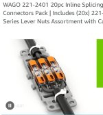
For connecting wires, i wonder how the new wago inlines would work?
Attachments
Id personally love to see a collaborative effort on this!
The tube tester presented in the video is for a grounded cathode circuit, so the topology of what circuit you want to test a tube in is the basic starting point for where to place the meters, plug pins, power sources, pots, etc. Grounded cathode is also the basis circuit for data sheets.
The output opamp and selector and input selector could apply to any topology you want to place a tube into grounded grid, cathode follower, concertina, long tail pair, etc. So I think that pretty much stays, you're always going to need input and output flexibility. I'd like to see a newer audiophile opamp used maybe NE5532 or TL072 than the TL022 he used. I'd also like to have more than the 1:10 voltage divider, I'd have switchable 1:100, 1:50, 1:20 and 1:10 so you can run tests at higher voltages and not blow out the opamp buffer. Other topologies would have different placement of the pin jacks, metering, assumptions, etc. Once a tester is developed for grounded cathode, others can be worked out as separate testers. I like the idea of keeping the power supplies separate like the video as most people already have their preferred bench supplies available. A switcher would just bring in noise. So bringing the voltages to the tester safely is all that is needed. What hardware people use for jacks, meters, etc. is less important than getting down the schematic and going through all the typical measurements and making the dial-in of voltages, resistances, etc. easy and fast.
I - of course - feel the opposite. I sold my big V regulated supply and could build this whole thing with that revenue. Since I'd bet there's more tubers interested than TubeLab or smoking-amp - folks who've collected up that type of equipment over decades - getting a power supply in order is the hardest part for a neophyte.I like the idea of keeping the power supplies separate like the video as most people already have their preferred bench supplies available. A switcher would just bring in noise.
As far as noise, well, we're engineers and I believe that could be dealt with, with a little pooge on the off the shelf item. This is, of course, in the context of signal tubes, with their milliamps of current draw.
Scoping out power tubes, you're - understandably - not going to get away with a $15 amzn purchase and perhaps a handful of additional components for the power supply part. Maybe that's OK - if there's any truth in "the guitar amp sound is all in the preamp" and one can simply follow that signal with a SS class D and all's good.
10X the headache to accommodate power tubes for what gain? OPTs are expensive; I suspect you can get whatever signature they impart on guitar sound by putting them in a different part of the circuit, using something smaller and far cheaper.
Hello Windcrest:
Here is another fellow that has published a wonderful series on the tube tester he designed and built. I think it might be a very good place to start a discussion. I attached #7 in the series as it gives a good summary and shows some examples.
He does not talk about topologies, yet that could easily be an extension once a tube is tested. The critical items are discussed.
I hope this helps
I see he built his own power supply - with even an OCP element. The D sub tube-card idea is certainly one way to keep B+ and fingers isolated!
So, once you have your tube instance profiled somewhere along the bad-good continuum, then what? Keep it / chuck it? The "competing" ideas allow one to see the tubes effect on an audio signal. I'm rooting for a live FFT harmonic analysis at various operating points, using REW and a USB I/O board.
A TubeLab type idea would allow that through a string of amplification stages, which would be nice to see before hard wiring into a chassis.
Curiously, could you create a reasonable audio amplifying topology with J-Fets, then match the tube's sonic behavior via analysis to that of the J-Fet. Then build once, turn it on and have it come out as expected - for small signals at least? J-Fets being somewhat less dangerous to prototype with...
Hello Windcrest:
Here is another fellow that has published a wonderful series on the tube tester he designed and built. I think it might be a very good place to start a discussion. I attached #7 in the series as it gives a good summary and shows some examples.
Yes I posted this one earlier in the thread. My thinking is for a device that serves both as a "tube tester" not so much to find bad tubes, but to find, experimentally, the operating point you like best in terms of harmonic distortion profile, voltages, power level, operating point, etc. IOW all the compromises able to be tried and dialed in so one can choose the best compromise. Then to be able to actually hear the grounded cathode circuit at that operating point. I imagine other standard tube circuits could be dedicated to other versions of the tester for grounded grid, cathode follower, even two tube circuits, etc. It might be a matter of just making a board with the rheostats and plug pins pre-wired for those other circuits as this tester is pre-wired for grounded cathode. When I have time I hope to start a schematic going. My concern about incorporating the power supply in the device is weight and bulk for the transformer. Especially if there are to be multiple versions of the "tube tester" wired up for different topologies, I'd have to duplicate the power supply in each one. Thats why for my taste I prefer all the power to be external and brought to the tester like Helge did. But anyone can do anything, even incorporate batteries for grid bias, no power supply at all there would be needed.
Another possibility is to have the metering, power supplies and input/output selectors in a "backplane" chassis. Then to work/learn different topologies (tube circuits). A board of that circuit type would drop onto the top of the box. Then you would select the plug board for whatever type of circuit you wanted to employ your tube in (grounded cathode, cathode follower, etc), select a tube base adapter (like Helge's tester does). Then wire it up and test. So basically the power supply, meter bridge and in/out with opamp, the output attenuator, etc. is in the base unit, but different plug boards with tip jacks get you the circuit context you want to test your tube within. Lay that board on top of the common backplane, wire it up and go. This allows you to share the common power, meters, etc with any plug board and the plug boards are pre-wired for totally different circuit types. Yeah, that's the ticket!
Last edited:
I see he built his own power supply - with even an OCP element.
OK my concern was for weight especially if I wanted to develop 5 different testers for five different tube circuit types, and having to repeat a heavy PSU in each one. But I think I have a solution, see my previous post. A backplane unit would contain the PSU, meter bridge, in/out selectors, opamp, attenuator. And to test your tube in the context of various circuit types there would be overlay boards that are pre-wired for grounded cathode, cathode follower, grounded grid, etc.. Youy would choose what overlay board you wanted to experiment with to operate the tube in that circuit type. So you have lightweight overlay boards with pin jacks pre-wired for many different circuit types. Once wired up the process of "dialing in" voltages, harmonics, resistances is pretty much what Helge does, but within the circuit type chosen. This way the heavy PSU is made common to any number of testing scenario pre-wire boards.
I am wondering if you might be mentally designing in a bit more complexity than is needed. A tube board that has jumpers for each pin allows for all pin out patterns. Topologies are jumper connections between boards.
I am thinking that a combination of the two designs might be a place to start.
I also like a separate power supply module or perhaps a suitcase design to primarily house the power supply, meters, poentiometers, with plug in boards for various tube sizes. If a person wants to explore output stages then that will also add the complexity of output impedance, and transformers. That might be a bridge too far.
True, but clips and bare metal connectors leaves open the possibility to get the tip of your fingers blown off. The overlay board does not, as (I assume) HV connections would end up happening deep between the two mated surfaces. Safety being a bit more difficult to physically accommodate.A tube board that has jumpers for each pin allows for all pin out patterns.
Makes me wonder if the OCP circuit could be setup to run a signal tube just fine, but cause minimal "damage". I dont happen to be familiar with shocks from 250V at just 5 mA, so perhaps it's moot. Gotta be better than contact to 250 across 100uF from a solid wire -
My last plug for the amzn power supply - or one like it - is it'd be possible to run off a battery. Pretty sure I bought a 6AH 12V from the same for ~$20. No AC line involved at all; battery laptop generating a signal, doing analysis, battery powered tester. For signal level tubes, like a 12AX7...
Had an idea for safer clips around tubes. Could use a food container, like cottage cheese or similar. Cut a whole in the bottom center for the tube. Cut the sides down so it's just deep enough to cover the pins. Drop it over the tube/pin assembly to cover exposed metal. Wires/leads get flattened to board surface to pass under it, or cut some scalloped edges to pass wires thru. You'll need some insulating "spaghetti" tube to put over the remaining exposed component leads.
Last edited:
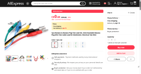
when I suggested jumpers I should have explained further. 4mm bannana plugs can be purchased in a stackable design. I use these.
They are also available in in 2mm size for an even more compact design.
These work great and fit tight together. I do not have to worry about tube base pin out patterns. You can get them in various lengths upto 1m long.
They are also available in in 2mm size for an even more compact design.
These work great and fit tight together. I do not have to worry about tube base pin out patterns. You can get them in various lengths upto 1m long.
Attachments


Shrouded banana and tip plugs are available for safety, Banana and tip jacks are safe too. I like Helge's use of standard banana and tip jacks, but he used binding posts for the feed lines, I'd make those just regular banana jacks.
SCD: I know I'm overcomplicating it by dedicating the overlay boards per topology, I'd even envision the overlay boards have their schematic printed on it joining the various jacks. Complexity has to go somewhere in all things technical. For a beginner, learner, you don't want that complexity to be conjured up by them, but to teach them, experimentally, how a certain type of tube circuit behaves, by letting them twist dials. Presenting a pre-wired plug board for whatever circuit type they want to explore, vary, measure, listen to...
You can see where I'm headed... A classroom device for a student, a tube tester, a "try it out" tool for an advanced person, etc. No need to hunt down a schematic, just grab the circuit type plug board you want, grab a tube or two and their sockets, then wire it up according to the instructions and schematic printed right on the plug board. Then power it and experiment, learn how to use your scope, analyzer, ears, etc. A total departure from spice.
The T30-2 wire grabbers from Ebay arrived this morning. They are obviously old and a bit tarnished but will work fine for my breadboard use. These will be used in the construction of several breadboards, each of which will contain one tube socket and the parts for a minimally functional circuit block using the T30 clips to allow for easy solderless parts changing where the dip switch and resistor bank is not feasible. The circuit blocks will be things like a pentode gain stage, phase inverter, dual gain stage with a twin triode tube, FMV triode stack between two triodes. Baxandall tone stack between two triodes.......
I must caution the readers of a possible rabbit hole that I wandered down about 20 years ago and spent several months wandering around before exiting with more questions than answers.
I mention breadboard gain stages, and I will indeed take all of the usual measurements, run signals through them and analyze the results, and listen to audio that is run through one or more of these stages. I have been there, done that before, and it is a worthwhile endeavor, if only for the knowledge gained. All of this went as expected with small signal tubes. I still have large bags, and boxes full of untested loose tubes, some of which are in large quantities. At one time I had three tube testers......
The following is a quote from me written over 7 years ago in post #2043 in the HBAC challenge thread:
"At one time I had 3 tube testers. One basic emission tester, and two transconductance testers. I found that none of these could reliably weed out all bad tubes. I had a big bag, maybe 250 used 6U8 tubes and a KT88 HiFi amp design that used them. I ran all of the tubes through the amp, testing for DC voltages, gain and distortion. I ran maybe 30 or 40 tubes through the amp, ran the stats for all the tubes using the 6 sigma tools that I had been taught during my engineering career at Motorola to determine the specs needed to ensure that every tube that I tested would work in the amp.
I then ran all of the tubes through the amp, and tested each one to those specs. There were maybe 20 tubes that didn't make the cut, each rejected for one or more out of spec parameters. None of the tube testers could reliably find those bad tubes, and one of them failed several good tubes. The transconductance testers did a decent job of finding the tubes that failed the DC specs, but couldn't find those with high distortion, and some were really bad.
After that experience, maybe 12 years ago, I sold all the tube testers.
Another forum member who wants to remain anonymous has sent me a vacuum tube curve tracer. I had about a day to play with it last year, but it really needs to find a spot on a workbench and a dedicated oscilloscope. I really want to run a big bag of tubes (I have several) through a curve tracer then stick them all into a working circuit. That will be a learning experience, then maybe we can all figure out how to build a tube tester that really works."
Clearly there was something going on in some tubes that a tube tester did not find, and some false "bad" tubes that did not matter.
I spent some time chasing it, eventually breaking several of the high distortion tubes to look for anomalies, but never found anything conclusive. The 6U8 tubes in question were used in a two stage circuit that used the pentode section for voltage gain and the triode section at a split load phase inverter. The unexplained distortion was traced to the pentode section. Minor tweaks in the operating conditions (power supply voltage) did affect the distortion in some tubes. After a couple weeks of tinkering my ADHD powered brain wandered off and the "bad" 6U8's were forgotten.
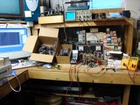
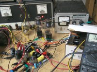
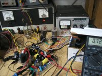
Sometime later I had "invented" the amp called the TSE. I had exactly one of them built on a home made PCB with no case. It used 45's, 2A3's or 300B's. Seen here testing OPT's with 300B's. I had run it with 45's and 2A3's before taking this picture. The 6A3 tube is a 2A3 with a 6 volt filament, but I have never seen one. A 6B4 is a 6A3 with an octal base and they were quite common in military surplus in the late 1990's. I had lots of them. The next picture shows 6B4's connected into the TSE with clip leads and an external heater supply. Back around 2000 there was an "urban vacuum tube legend" about some rewired 6AV5 tubes that were marked 6B4GA and sold by Sylvania to the military to fulfill government contracts. The tubes had been seen on the surplus market occasionally, but nobody seemed to have any or even a believable picture, so it went down as fokelore......until I found one of the actual tubes. Unfortunately it had a white getter. So what do I do? Well there is already sole octal sockets hanging on the ends of some clip leads, so I rewire the sockets and stick a pair of 6AV5's into the TSE and flip the switch.
I spent some time turning knobs, swapping OPT's, and tubes, and just tinkering with the ball of clip leads. I ran all sorts of measurements, and listened to a good bit of music, and made the rabbit hole open up in front of me.
I found that while feeding a 1KHz tone through the amp with a load resistor in place of the speaker I could null the third harmonic down to -50 to 60 db by tweaking the bias current and plate supply voltages. The null could only go down to the -20 to 30 db range while connected to a speaker. There was a much sharper null with a small Edcor OPT, almost to the limit of my PC / sound card analysis system. Again, this was greatly reduced by connecting a speaker.
None of this seemed to matter as I ran the amp through the range of currents and voltages seen in these tests with music playing through the same speakers. This led be to the question as to what the speaker did to upset this null. All of this took place over 20 years ago according to the dates on the pictures. The Speaker VS Amp rabbit hole thing occurred after finding the mysterious third harmonic null, but I can't find those pictures.
I must caution the readers of a possible rabbit hole that I wandered down about 20 years ago and spent several months wandering around before exiting with more questions than answers.
I mention breadboard gain stages, and I will indeed take all of the usual measurements, run signals through them and analyze the results, and listen to audio that is run through one or more of these stages. I have been there, done that before, and it is a worthwhile endeavor, if only for the knowledge gained. All of this went as expected with small signal tubes. I still have large bags, and boxes full of untested loose tubes, some of which are in large quantities. At one time I had three tube testers......
The following is a quote from me written over 7 years ago in post #2043 in the HBAC challenge thread:
"At one time I had 3 tube testers. One basic emission tester, and two transconductance testers. I found that none of these could reliably weed out all bad tubes. I had a big bag, maybe 250 used 6U8 tubes and a KT88 HiFi amp design that used them. I ran all of the tubes through the amp, testing for DC voltages, gain and distortion. I ran maybe 30 or 40 tubes through the amp, ran the stats for all the tubes using the 6 sigma tools that I had been taught during my engineering career at Motorola to determine the specs needed to ensure that every tube that I tested would work in the amp.
I then ran all of the tubes through the amp, and tested each one to those specs. There were maybe 20 tubes that didn't make the cut, each rejected for one or more out of spec parameters. None of the tube testers could reliably find those bad tubes, and one of them failed several good tubes. The transconductance testers did a decent job of finding the tubes that failed the DC specs, but couldn't find those with high distortion, and some were really bad.
After that experience, maybe 12 years ago, I sold all the tube testers.
Another forum member who wants to remain anonymous has sent me a vacuum tube curve tracer. I had about a day to play with it last year, but it really needs to find a spot on a workbench and a dedicated oscilloscope. I really want to run a big bag of tubes (I have several) through a curve tracer then stick them all into a working circuit. That will be a learning experience, then maybe we can all figure out how to build a tube tester that really works."
Clearly there was something going on in some tubes that a tube tester did not find, and some false "bad" tubes that did not matter.
I spent some time chasing it, eventually breaking several of the high distortion tubes to look for anomalies, but never found anything conclusive. The 6U8 tubes in question were used in a two stage circuit that used the pentode section for voltage gain and the triode section at a split load phase inverter. The unexplained distortion was traced to the pentode section. Minor tweaks in the operating conditions (power supply voltage) did affect the distortion in some tubes. After a couple weeks of tinkering my ADHD powered brain wandered off and the "bad" 6U8's were forgotten.
Sometime later I had "invented" the amp called the TSE. I had exactly one of them built on a home made PCB with no case. It used 45's, 2A3's or 300B's. Seen here testing OPT's with 300B's. I had run it with 45's and 2A3's before taking this picture. The 6A3 tube is a 2A3 with a 6 volt filament, but I have never seen one. A 6B4 is a 6A3 with an octal base and they were quite common in military surplus in the late 1990's. I had lots of them. The next picture shows 6B4's connected into the TSE with clip leads and an external heater supply. Back around 2000 there was an "urban vacuum tube legend" about some rewired 6AV5 tubes that were marked 6B4GA and sold by Sylvania to the military to fulfill government contracts. The tubes had been seen on the surplus market occasionally, but nobody seemed to have any or even a believable picture, so it went down as fokelore......until I found one of the actual tubes. Unfortunately it had a white getter. So what do I do? Well there is already sole octal sockets hanging on the ends of some clip leads, so I rewire the sockets and stick a pair of 6AV5's into the TSE and flip the switch.
I spent some time turning knobs, swapping OPT's, and tubes, and just tinkering with the ball of clip leads. I ran all sorts of measurements, and listened to a good bit of music, and made the rabbit hole open up in front of me.
I found that while feeding a 1KHz tone through the amp with a load resistor in place of the speaker I could null the third harmonic down to -50 to 60 db by tweaking the bias current and plate supply voltages. The null could only go down to the -20 to 30 db range while connected to a speaker. There was a much sharper null with a small Edcor OPT, almost to the limit of my PC / sound card analysis system. Again, this was greatly reduced by connecting a speaker.
None of this seemed to matter as I ran the amp through the range of currents and voltages seen in these tests with music playing through the same speakers. This led be to the question as to what the speaker did to upset this null. All of this took place over 20 years ago according to the dates on the pictures. The Speaker VS Amp rabbit hole thing occurred after finding the mysterious third harmonic null, but I can't find those pictures.
Attachments
- Home
- Amplifiers
- Tubes / Valves
- This guy is doing this hobby the way I always wanted to do it