.................. On the D3 LED Anode should be close to 4 V(two LEDs voltage drop). Do the LEDs alight?
BR Damir
............. LEDs glow brightly.
..................
Maybe these are LED+RESISTOR instead of LED !.............. What kind of a LEDs you use that you have 5V drop on them? Or maybe you have to high current, it should be about 3.1mA to 3.2mA through them...................
Maybe these are LED+RESISTOR instead of LED !
......LEDs glow brightly.
Strange that LEDs glow brightly, at 3mA it should not, maybe some short connection at DN2535 mosfet??
Sorry, I just woke up and reading the replies, I noticed that I noted the wrong voltage on the base of Q3&Q4. It should read 5.5V. The LEDs are green jellies. I will go through my supplies and find some that only drop 2V each. Hopefully that is the issue.
Can you please attach the asc file? That would be very helpful.
Blessings, Terry
Can you please attach the asc file? That would be very helpful.
Blessings, Terry
Sorry, I just woke up and reading the replies, I noticed that I noted the wrong voltage on the base of Q3&Q4. It should read 5.5V. The LEDs are green jellies. I will go through my supplies and find some that only drop 2V each. Hopefully that is the issue.
Can you please attach the asc file? That would be very helpful.
Blessings, Terry
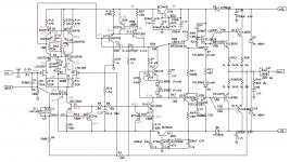
I don't think that the type of the LED is the problem, but the Vbe of Q3 and Q4, 0.5V is to low. Tray to check the LED's current. You can do that by measuring voltage drop on R42, the mosfet source resistor. It should not be higher than 3.2mA, .asc attached.
BR Damir
Attachments
Hi Damir,
Thanks for the asc file. I have been playing around with it this morning trying to simulate my condition. I swapped in blue LEDs and the only thing that really changes is the voltages around the base and emitter of Q3&4. Everything else stays about the same. So I doubt that is my problem. Also, I was concerned about the low vbe of Q20, but in the sim it is only .15v. I even pulled Q20 in the sim and it makes no difference at all. So I have some questions.
1) What is the purpose of Q20?
2) What determines the voltage at the base of Q15? Is it the diode drop across Q15 or does it come from Q4 & Q5?
3) Same question for Q12
Thanks, Terry
Hi Damir,
Thanks for the asc file. I have been playing around with it this morning trying to simulate my condition. I swapped in blue LEDs and the only thing that really changes is the voltages around the base and emitter of Q3&4. Everything else stays about the same. So I doubt that is my problem. Also, I was concerned about the low vbe of Q20, but in the sim it is only .15v. I even pulled Q20 in the sim and it makes no difference at all. So I have some questions.
1) What is the purpose of Q20?
2) What determines the voltage at the base of Q15? Is it the diode drop across Q15 or does it come from Q4 & Q5?
3) Same question for Q12
Thanks, Terry
Hi Terry,
Q15 and Q12 are EF enhanced VAS, Q20 is there to prevent VAS overload. It is normal to have 0.15 Vbe as it's passive in normal operation. The voltage at the base of Q15 comes from Q4, Q5 and that voltage is not correct. Don't look at Q15, the fault is not there, is in the LTP part as I said before. Check DN2535. The LEDs different voltage drop is not reason for thee fault, as you put more then two LEDs or even 10V zener and all will function correctly.
BR Damir
Yes, Checked all the jumpers, transistors, resistors. All the voltages are as expected in the LTP except for the collectors of Q4 & 5. which are about 1V too high. So the question is why?
Both boards are doing the exact same thing. Not sure what else I can check.
Terry, have you measured the CCS (DN2535) current(voltage drop on R42)? It shoud be about 1.4V and that gives about 3mA.
If that is OK, then is something wrong with cascade transistors(Q3, Q4) as you said there is only 0.5V between base and emitter and should be 0.6V. Are you sure those are 2SC2240?
PS. Could you check the PCB layout carefully as you are the first one to use this layout. I checked it again and could not find any fault but more eyes are better.
Last edited:
Yes, 1.45V across R42. Yes, genuine 2SC2240. I have tried my best to follow each trace and verify the circuit. So far I have not been able to find an error. I have plenty transistors so I will replace the LTP with more matched pairs on one board and see what happens. I am getting the same readings from both boards so it is unlikely that it is a bad transistor but who knows.
Thanks, Terry
Thanks, Terry
Yes, 1.45V across R42. Yes, genuine 2SC2240. I have tried my best to follow each trace and verify the circuit. So far I have not been able to find an error. I have plenty transistors so I will replace the LTP with more matched pairs on one board and see what happens. I am getting the same readings from both boards so it is unlikely that it is a bad transistor but who knows.
Thanks, Terry
What 2SK170 type you use, 2SK170BL I hope? That is main difference as the board is for LSK389B.
Hi Damir,
Yes, I used 2SK170BL. I matched them and swapped the drain and source legs so I could mount them face to face and thermally couple them. I tried but couldn't find the LSK389B anywhere.
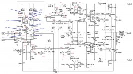
I just checked my measurements and I misstated earlier. I have 1.55V across R42. That is 3.3mA. I am attaching a corrected schematic.
Yes, I used 2SK170BL. I matched them and swapped the drain and source legs so I could mount them face to face and thermally couple them. I tried but couldn't find the LSK389B anywhere.
I just checked my measurements and I misstated earlier. I have 1.55V across R42. That is 3.3mA. I am attaching a corrected schematic.
Attachments
Hi Damir,
Yes, I used 2SK170BL. I matched them and swapped the drain and source legs so I could mount them face to face and thermally couple them. I tried but couldn't find the LSK389B anywhere.
I just checked my measurements and I misstated earlier. I have 1.55V across R42. That is 3.3mA. I am attaching a corrected schematic.
Hi Terry,
That is OK, 3.3mA is not to much. I simulated with some resistor(20k) across Q15 base-collector and the voltages became very similar to yours. I suggest to change Q15, maybe you can't detect this error with ordinary ohmmeter.
BR Damir
terry:
-are you sure the P2 trim pot is centered? (voltages at the jfet sources suggests not)
-are you sure the jfets are correctly wired? (these devices can have source/drain reversed and still work just fine, but get the gate wrong and all bets are off!)
also, it concerns me the voltage around the bias regulator is not symmetrical, should be maybe +/-6v (for example) instead of -0.75/-13v.
also, should be almost 0.2v across R29; looks like 0 now. damir may be on to something with Q15 (or Q12) being wacky ...
Q15 is not on and it should be. are you sure Q15 base is well soldered to pad?
good luck,
mlloyd1
Last edited:
Hi Mlloyd,
You are right that P1 wasn't centered. I noticed that but since the emitters of Q3&4 were so close I didn't worry about it. The bias reg is off because Q12 and Q15 are off.
Damir,
I change out Q15. The one I pulled measures perfectly out of circuit but I went ahead and installed a new one. I also replaced the green LEDs with some yellows I had that measure closer to 2V each. I am attaching and updated schematic. As you can see, the base of Q15 is still a volt too high.
Blessings, Terry
Attachments
Hi Mlloyd,
You are right that P1 wasn't centered. I noticed that but since the emitters of Q3&4 were so close I didn't worry about it. The bias reg is off because Q12 and Q15 are off.
Damir,
I change out Q15. The one I pulled measures perfectly out of circuit but I went ahead and installed a new one. I also replaced the green LEDs with some yellows I had that measure closer to 2V each. I am attaching and updated schematic. As you can see, the base of Q15 is still a volt too high.
Blessings, Terry
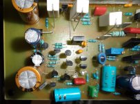
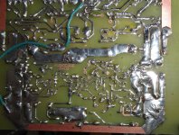
Way do you have different voltage on Q4 Q5 collectors and Q15 base, or you did not measure that again? I simulated with Q15 base disconnected and Q4 Q5 collectors showed same voltage as you have measured. I am getting out of ideas. Could you take a close photos from top and bottom that LTP VAS part?
BR Damir
PS. have you measured 2SK170 Idss?
Last edited:
Strange, when I sim with Q15 base disconnected I get 1.2V on Q4 collector.
I will take some pics.
I will repeat the question about 2SK170, have you measured Idss before it was soldered?
We concentrated on bipolars, maybe the problem is nfet.
PS. If you disconnect Q15 base you need to ground the J2 gate otherwise reading is strange.
Last edited:
- Status
- This old topic is closed. If you want to reopen this topic, contact a moderator using the "Report Post" button.
- Home
- Amplifiers
- Solid State
- ThermalTrak+TMC amp