hehe, test result confirms yer listening. HF response is not very flat. maybe you have a wrong part by two decimal places somewhere,
It's usually good form to show the attenuator baseline to rule out test fixture issues
remove shunt cap at input and/or check amp gain.
It's usually good form to show the attenuator baseline to rule out test fixture issues
remove shunt cap at input and/or check amp gain.
Last edited:
Good work... enjoy them playing..
i'll suggest you to plan a new board with SMD resistors and caps if possible, it will make it further compact...
on the other hand i myself once was carried away with the idea of compact PCBs for both LM3886 and LM4780 and i designed them also, but later i had problems in soldering the parts and any replacement is further too difficult. DIY Audio Amplifier Blog: Evolution of PCB for LM4780 based amplifier.
DIY Audio Amplifier Blog: Lm4780 Single Sided PCB v3
So what i learned from that compact layout is no much useful if components are too close. In diy pcbs, the soldering becomes very difficult, soldering flux leakage is there & induce stray inductance on PCB which may deterioration of signal quality. Troubleshooting is more difficult.
So now i started planning little spacious layouts but maintaining shorter track paths.
Last edited:
New results ") Thanks for quick responses everyone! (esp. Infinia).
Thanks for quick responses everyone! (esp. Infinia).
As you can see in the description, the measurements were made minus the compnents listed.
Now its pretty obcious cn/cd were much too big with 100nF.. now that I can see the results 100_p_F might have been better.. or leave them out entirely? What are your thoughts?
happy cheers!
P.s.
Thanks for quick responses everyone! (esp. Infinia).As you can see in the description, the measurements were made minus the compnents listed.
Now its pretty obcious cn/cd were much too big with 100nF.. now that I can see the results 100_p_F might have been better.. or leave them out entirely? What are your thoughts?
An externally hosted image should be here but it was not working when we last tested it.
happy cheers!
P.s.
An externally hosted image should be here but it was not working when we last tested it.
Last edited:
Those measurement curves show some serious problems. Is the trace in the upper window the soundcard looped back to itself? If so, you need to correct that first.
Mike
No, it was both the AMP, soundcard loopback is fine, didn't know there was a mono-mode, so I probably picked up some noise fromthe open line. Now THD with 0.0004 is much better!
cheers!
No it's good to limit the bandwidth, to prevent RF IMD and slew rate limitations albeit all this should take place beyond the human hearing. Now that you have the measurement tools. I would practice with RMAA chart presentations ie normalize the test fixture attenuator to show accurate amp gains etc.
see 100 Hz and it's harmonics is dominate, that's the power supply and chip amp PSRR
50 Hz is usually some ground loop leakage.
Now that you have the measurement tools. I would practice with RMAA chart presentations ie normalize the test fixture attenuator to show accurate amp gains etc.see 100 Hz and it's harmonics is dominate, that's the power supply and chip amp PSRR
50 Hz is usually some ground loop leakage.
Last edited:
Poof said the soundcard... there goes my right line-in channel. Due to an unfortunate incident, an RCA-cabel with the center pin, being connected to the surrounding copper, there can be no stereo-tests any more :-(
These things really make me paranoid...
But on the bright side, the stereo-configuration is up and sounding really well. On party volume the supply-voltage drops at a maximum of ~3V under heavy bass, from 27 to 24V.
The supply-toroidal is an 18V 80VA model.
Heatsinks are 2.2K/W with thermal grease and lm3886TF as calcualted they get warm but not hot.
will keep you posted!
The whole RF-issue with cd/cn will be addressed at some point, but not right now since I don't have any spare caps lying around and will wait until I have enaugh stuff together for ordering.
cheers!
sorry about your loss,
next up for protection of sound card test eq. build a couple of op-amp buffers with diode clamps.
80-VA is about right for a mono-block along with picking the output voltage to sag just right for 4 ohm speakers ~ 2*28V AC no load.
160 VA is good for a stereo pair and offers much better load regulation at 2*25V AC
Last edited:
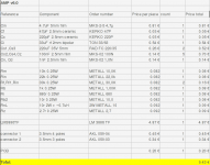
So 9 month later the Amp is still playing fine and its time for some more fine-tuning.
First, the gain has to be adjusted, it is a bit too low. From 33 now to 44.
That is, rf and rf1 will be raised from 22k to 30k.
Cn and Cd will be reduced from 100nF to 1nF for rf filtering. 100nF was way too much (as you can see in the rmaa test charts).
A few parts got shifted around, the LM3886 was moved a little higher.
So this is v6.0
And the updatet parts list.
cheers!
hurtz
First, the gain has to be adjusted, it is a bit too low. From 33 now to 44.
That is, rf and rf1 will be raised from 22k to 30k.
Cn and Cd will be reduced from 100nF to 1nF for rf filtering. 100nF was way too much (as you can see in the rmaa test charts).
A few parts got shifted around, the LM3886 was moved a little higher.
So this is v6.0
An externally hosted image should be here but it was not working when we last tested it.
And the updatet parts list.
cheers!
hurtz
Attachments
I would not fit Cn to the PCB. I would fit it across the signal input socket, hot to return. Maybe a value of 47pF instead of 1nF.
I would also experiment with Cd. Try a range from 330pF to 1n5F.
I am not sure you need Cc and Cd and Cn, That is three low pass filters on the input.
If keeping all three is best then again I recommend reducing Cc. At the moment there must be quite a cut in the high treble, with all three at the values you have used.
Why did you choose 680r (Ri) and 33uF (Ci) for the NFB bass roll off?
(edit: I have just read post101, surely not because 33uF is physically small)
I like the layout and the way you have included so many options.
Last edited:
It appears you are using only one common wire for all ground connections back to the power supply, if so, doing it this way will definitly increase THD and noise. And using an "isolation resistor" between the signal and power grounds doesn't really solve the problem, it just sweeps it under the rug. I strongly advise using separate ground connections for for the signal and power at minimum. I have the signal, power, and speaker grounds all individually connected to the power supply common ground on everything I design and build. It's the best way to do it, and even better, it's cheap and easy.
Miike
Miike
No.It appears you are using only one common wire for all ground connections back to the power supply,..........
I see the Power Ground coming from the two stages of decoupling coming back to the PSU Zero Volts. I also see the Zobel Return coming back to the PSU Zero Volts.
I see the PSU Zero Volts sending a single trace connection to the Signal Ground on the PCB.
The Signal Ground has connected to it:
1.) the voltage reference for amplifier Main Audio Ground
2.) the NFB lower leg
3.) the resistor defining Rin
4.) the capacitor defining the on board RF filter attenuation
5.) the indirect connections to both -IN and to +IN
6.) the connection for Signal Return to complete the input circuit.
What I see cannot be described by your phrase
one common wire for all ground connections back to the power supply
Last edited:
Once agian, ALL of the low current and high current ground paths are routed to a single point (lower left corner on the PCB lay-out), and then A SINGLE WIRE is used to connect all of them back to the power supply common ground (0-volt if you prefer.) It would be better to run the low current and high current ground conections from the amp board to the power supply through thier own individual conductors. I always use at least three separate ground paths for my designs, one for the input and feedback (low current) paths, one for the local power supply de-coupling, and one for the speaker/output zobel path.
Mike
Mike
I would not fit Cn to the PCB. I would fit it across the signal input socket, hot to return. Maybe a value of 47pF instead of 1nF.
Check!
I am not sure you need Cc and Cd and Cn, That is three low pass filters on the input.
Cn on the RCA and Cc right on the input pins seem to be a good idea. Concerning Cd I think I just have to do some tests to see how it will perform with and without.
With a look at post #184 removal of both Cn and Cd led to a considerable amount of increase in noise.
Sadly I only have a creative soundblaster x-fi usb sound card at hand which will most probably limit my ability to test any change in THD and Noise.
Why did you choose 680r (Ri) and 33uF (Ci) for the NFB bass roll off?
(edit: I have just read post101, surely not because 33uF is physically small)
Hmm well yes I did, the next bigger bipolar capacitor has a 14mm (+2mm) diameter so it doesn't fit.
However I don't quite get the idea behind the size of the capacitor. Ri and Rf + Rf1 set the gain and the combination of Ri and Ci set the aforementioned NFB roll off.
But since this is the negative feedback that ties into the negative input, 33uF should be plenty for the low level(?)
(As enzoR mentioned quite some time ago it is possible to use two monopolar caps connected at the negative leads to make one bipolar... there actually is room for a bigger Ci)
@Mike
Please take a look at post #159, the PSU doesn't have a common 0V point, so the "master" 0V is on the AMP board, no point in shifting it to the PSU.
Thank y'all for your input!
Cheers!
hurtz
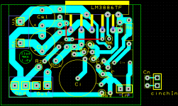
AMP v6.1
Attachments
Don't use a bi-polar.
A polar electrolytic is adequate. It is cheaper. It allows more capacity for the same size.
If you want to add protection to the electrolytic then add a diode across the cap or two diodes in inverse parallel. This protects the cap if the amp output ever fails to either supply rail.
Aim for at least half an octave below the passive high pass input filter.
Ok, here is what I got: (please excuse if my posts are overly detailed)
Passive highpass input Filter: Rin + Cin
So half an octave would be a perfect fourth with a ratio of 3:4. which would be 1.16Hz or lower.
I'm not quite sure why Ri would be the corresponding resistor since it is connected in series with Ci. But Rf or Rin results in a C of ~5uF which doesn't fit to the claim that 33uF is not enough.
Since I'm already using 220uF capacitors for the input pins, one of them will be used here as well.
---
As an additonal thought I'm thinking about a multichannel-Amp i.e. 5 or 7 channels.
The setup would be the same as with stereo, one PSU for two AMPs. All connected to one large toroid. Any thoughts?
---
Cheers!
hurtz
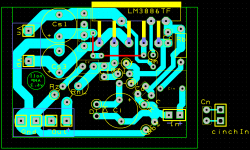
AMP v6.2
Passive highpass input Filter: Rin + Cin
Code:
Rin = 22k
Cin = 4µ7
f = ?

f = 1 / (2 * 3.14 * 22000 * 0.0000047) = [B]1.54Hz[/B]
So half an octave would be a perfect fourth with a ratio of 3:4. which would be 1.16Hz or lower.
I'm not quite sure why Ri would be the corresponding resistor since it is connected in series with Ci. But Rf or Rin results in a C of ~5uF which doesn't fit to the claim that 33uF is not enough.
Code:
Ri = 680R
Ci = ?
f <= 1.16Hz

C = 1 / (2 * 3.14 * 1.16 * 680) = [B]201.87uF[/B]
Since I'm already using 220uF capacitors for the input pins, one of them will be used here as well.
---
As an additonal thought I'm thinking about a multichannel-Amp i.e. 5 or 7 channels.
The setup would be the same as with stereo, one PSU for two AMPs. All connected to one large toroid. Any thoughts?
---
Cheers!
hurtz
AMP v6.2
Attachments
220uF on the input PINs?Code:Ri = 680R Ci = ? f <= 1.16Hz C = 1 / (2 * 3.14 * 1.16 * 680) = [B]201.87uF[/B]
Since I'm already using 220uF capacitors for the input pins, one of them will be used here as well.
You meant 220pF. 0ne million times smaller.
BTW,
where did the control function "code" come from?
Is it written in the Forum literature somewhere?
220uF on the input PINs?
You meant 220pF. 0ne million times smaller.
BTW,
where did the control function "code" come from?
Is it written in the Forum literature somewhere?
Sorry I meant Cs1/Cs3. I used the code function to make it look better.
cheers,
hurtz
- Status
- This old topic is closed. If you want to reopen this topic, contact a moderator using the "Report Post" button.
- Home
- Amplifiers
- Chip Amps
- The yet tiniest single-sided LM3886?