Back again... So I've pretty much soldered everything on both the rework version of the "The Wire" and a bi-polar power supply I got from glassware as per the recommendation of jdkJake...
PS-12 Bipolar Low-Voltage PS
I'm going to use a 50k RK27. Then I need to buy a few more parts like isolated RCAs, a fuse holder, IEC socket, volume knob, and a custom chassis.
I have a few questions before I embark on this part of the process. Besides tying the IEC jack to the chassis for safety ground, would I need something like a ground loop breaker with this amp tied to safety ground as well? I plan on having my RCA jacks isolated so I'm hoping it's not a problem.
I'm also planning on using Belden 8451 cable that I can get from work. Any reason not to use this stuff? It works fine for general audio cable so I figure it'd work fine here.
For my power switch I have a MTS-2 toggle switch that has 3 points on each side for a total of 6. Any reason I can't use this as a power switch?
Finally, I'm not sure if I should wire this up for star ground. Is this method even possible for this amp? Otherwise, if I don't my signal ground is floating, right? I know, I should read the audio grounding article to understand this further.
TIA
@Mull3t, I say you get the The Wire PSU kit and bolt it with the SE-SE as I did shown in pages 17 and 19 of the build thread. That saves you 4 holes on the chassis bottom and conceals the wiring between the PCBs that can otherwise be turning off to view, if it fits in your chassis. The bolt pattern for that combo is 22.5mm x 96.0mm.
http://www.diyaudio.com/forums/head...rate-build-thread-impressions-gallery-17.html
Ground loop breaker is against the safety rules unless it's done right. Usually a pair of backward parallel connected diodes are connected across the ground breaker switch to go compliant with the safety code.
I hooked up the RCA ground pins directly to the IEC socket ground pin with heavy gauge wires, and I always use interconnect cables that have heavy gauge ground conductor or those can be constructed to have a heavy gauge ground conductor in between audio gears, Mogami 3173 for example, in order to minimize the voltage drop over the ground conductors by the ground loop current if any. In my The Wire headphone amp the PSU/SE-SE combo has a single ground connection to the RCA ground pins through the shield conductor of the audio signal connections.
The SE-SE has an input impedance of 11k I'd use a 2K or maximum 5k type A taper pot to get a relatively even volume change across the dial range. With a 50k pot, though I've never tried myself, you'll probably get little volume change when you turn it up until you are approaching the maximum end of the travel.
One reason I can think of not using a DPDT power switch is that you wasted a pair of contacts and you have to cover these un-used pair of pins up with insulation to comply with safety code.
Standoffs....check ebay. I got mine there sometimes when a good deal pops out.
Last edited:
Nice! Doin' it doggy style! I saw that in the impressions/build thread while looking for casing options and for clues on how people are wiring things up. It's a shame that not many people have posted what they've done. By the way, I actually plan on using this chassis -- Tube Amp Chassis DIY 13x10x2 Aluminum Project Box Enclosure Stereo Amp Preamp | eBay from eBay. I'm thinking of trying to find a nice wooden knob to go with it. The gentleman building it will drill holes for me because I don't have a clean method of doing this.
I don't have an option as far as the PSU kit goes. As you probably know, they are no longer available. Unless you know someone that has a PCB still available?") Otherwise, I already have the PS-12 built.
Otherwise, I already have the PS-12 built.
So the method found on amb.org/beta22 isn't doable ie safe? Here's a excerpt from their website...
"For option 3 above, the ground loop breaker is a 10Ω 5W resistor in parallel with a 0.1µF capacitor rated at least 250VAC. For safety this capacitor should be rated for class X or Y (good for across-the-line use) with flame retardant casing. The ground loop breaker should be connected between the signal ground and the chassis (which is in turn connected to AC earth ground via the IEC power entry receptacle). Mount the resistor and capacitor in a secure manner so that it will not come loose and come into contact with other circuitry. A good way to do this is to use a terminal strip."
I would prefer not to have to wire up a ground loop breaker at all. I guess I won't unless I need it. You mention a switch. Why would you want to turn the ground loop breaker on and off?
With regard to grounding... so you're connecting two wires each to the both RCA ground terminals? One that goes to the IEC socket pin, and the other that goes to your pot? Is this correct? Is your IEC socket pin also connected to the chassis? Do you have a close up pic that illustrates this?
I'm still not understanding "how to choose a proper pot" works. For now, I'll give the 50k RK27 a shot because I don't have anything else. I've been using them on my two Cavalli Compact Tube Hybrid amps and thus far no issues with attenuation. I can barely get the volume past 12 o'clock without blowing my ears off. Can you explain it a little further in a not too technical way?
Sometimes I need the semi-non-technical way first to wrap the head around how something works. Plus I think it's a benefit for other relative noobs as well.
I'm going to go ahead and buy a new SPST switch since I have to do a Mouser order anyways.
Thanks for the help.
I don't have an option as far as the PSU kit goes. As you probably know, they are no longer available. Unless you know someone that has a PCB still available?
Otherwise, I already have the PS-12 built.So the method found on amb.org/beta22 isn't doable ie safe? Here's a excerpt from their website...
"For option 3 above, the ground loop breaker is a 10Ω 5W resistor in parallel with a 0.1µF capacitor rated at least 250VAC. For safety this capacitor should be rated for class X or Y (good for across-the-line use) with flame retardant casing. The ground loop breaker should be connected between the signal ground and the chassis (which is in turn connected to AC earth ground via the IEC power entry receptacle). Mount the resistor and capacitor in a secure manner so that it will not come loose and come into contact with other circuitry. A good way to do this is to use a terminal strip."
I would prefer not to have to wire up a ground loop breaker at all. I guess I won't unless I need it. You mention a switch. Why would you want to turn the ground loop breaker on and off?
With regard to grounding... so you're connecting two wires each to the both RCA ground terminals? One that goes to the IEC socket pin, and the other that goes to your pot? Is this correct? Is your IEC socket pin also connected to the chassis? Do you have a close up pic that illustrates this?
I'm still not understanding "how to choose a proper pot" works. For now, I'll give the 50k RK27 a shot because I don't have anything else. I've been using them on my two Cavalli Compact Tube Hybrid amps and thus far no issues with attenuation. I can barely get the volume past 12 o'clock without blowing my ears off. Can you explain it a little further in a not too technical way?
Sometimes I need the semi-non-technical way first to wrap the head around how something works. Plus I think it's a benefit for other relative noobs as well.
I'm going to go ahead and buy a new SPST switch since I have to do a Mouser order anyways.
Thanks for the help.
Hey Mull3t - nice find on the case! I'm always looking for a good quality case with wood accents. Seems like he's fairly flexible and willing to help out. Sounds like we're doing something similar (at least with how we're using wood). I'm going to have a wood 'cube' made, with a pot on top with a wood knob. IEC on the back (switched/fused), and a 1/4 headphone jack on the front. Something unique.
Hi Mull3t, I thought the ground breaker in your post was a switch some people would use in a component to lift the earth ground wiring from an IEC jack for breaking the inter-component ground loop when needed, and did not realized you were referring to the amb.org ground breaker. My apologies. However, that ground breaker in amb.org doesn't seem to be a good idea to me. The mains noise coming through the parasitic between the primary and secondary windings in a power transformer should be returned to the earth ground through a low impedance path, in my opinion. The application in the amb.org breaker seems to be doing just the opposite. Perhaps I didn't understand the idea behind it.
Yes I run two ground wires on the RCA jacks, one goes to the IEC ground pin, the other goes to the volume pot. I understand by theory that the 2nd ground from RCA should not go to the pot but to the center point of the power supply but because we are dealing with a very small current in a headphone amp and the layout of the SE-SE and the PSU ensure an extremely low impedance in the ground system I decided to make it that way to simplify the build.
I do have another ground wire off the IEC jack and it is tied to the center bolt of the transformer with a ring lug to ground the chassis.
If you find the 50K pot doesn't work as expected (un-even volume control) you may want to try increase the value of the 10K resister at the non-inverted input of LME49990 to 100kohm and see if it improves.
@Misterrogers -- yeah I was on a hunt for diy chassis that weren't from par-metal, etc and I came across this one. The size is going to be smaller than what's in the auction -- 6.5" x 8.25" x 2.5625" internally. I'm pretty stoked about this case.
@nattawa -- nope what I was referring to would prevent buzz. Some amps apparently require it depending on if you have your trafo in the same case. I'll have to do more research into how it's working and whether it's safe to do.
On my Cavalli Compact Tube Hybrid amps I've always connected the ground from the RCAs to the pot which is also tied to input ground or what I assume is virtual ground. Originally, if I didn't also loosen a screw on the RK27 I was using and tie another lead from that to the same location on the pot as the other ground connections I would get a buzz when I touched my volume knob. After doing this the buzz would go away.
I will try your method and see how things go.
All that being said... I'm almost to the point of wiring this puppy up and have a few questions before I do anything wrong. I'm looking to figure out what to have wired to where in this scenario...
I have an IEC jack with three pins, a SPST switch, an in-line fuse holder, and my transformer with primary (yellow*/black), primary (red*/violet) and secondary (green*/red), secondary (brown*/blue). What do I tie together and in what order in order to achieve 15-0-15? I just don't want to fry anything...
TIA
BTW, the RK27 body should be tied to chassis ground.
Only if you have a problem should you use a ground breaker between chassis ground and signal ground.
Ideally, all signal grounds should tie to a single point (star ground).
Earth ground on the IEC should tie to the chassis, provided it is metal.
Only if you have a problem should you use a ground breaker between chassis ground and signal ground.
Ideally, all signal grounds should tie to a single point (star ground).
Earth ground on the IEC should tie to the chassis, provided it is metal.
Last edited:
I ended up with that transformer you previously recommended to me -- the super small one from digi-key. Here is a pic of its schematic:
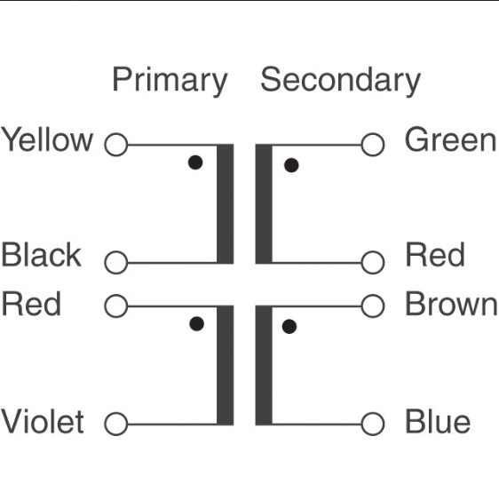
Not sure which one is mains and which one is neutral but if I were a betting man I'd say the yellow is mains and black is neutral. Same with red and violet. If I want to make a center tap and create 15-0-15 wouldn't green and blue be tied together and sent into CT on my supply? And then brown goes into one of the AC holes and red goes into the other?
In my CTH the RK27 is tied to input ground. This could be wrong, but it seems to be doing the trick. With this build I'll make sure to tie it to the chassis, which is metal. So yes the earth ground will be tied to it as well.
With regard to star ground, I'm assuming that everything can go to a terminal strip. I'm still not sure what goes there. But I'm assuming if the given pcb, jack, or pot has a ground point it would go to the strip so that every body is talking to each other. I'll write up a diagram with what I think is right.
Thanks!
For 115V operation and 15-0-15 output:
On the primaries, tie together yellow/red and black/violet. Hook those to your AC mains. I would hook yellow/red to hot and black/violet to neutral.
On the secondaries, tie together red/brown. This represents the center tap. Green is one of the 15 outputs and blue is the other. 15-0-15 = green-red/brown-blue.
When you say your rk27 is tied to input ground, are you referencing the body or the input pins? I am referencing the body of the pot (use on of the screws on the back and wire a loop to chassis ground).
Let's see what you come up with for grounding and we will go from there.
The PS PCB I'm using doesn't have an indication of which is hot or neutral. It just says AC and has two holes.
That being said, I think I got the jist of what's going on with the trafo with the exception of how to mix in pwr switch and fuse holder. I'm going to guess that the yellow/red go directly to the board of the first AC hole. Then black/violet go to one side of fuse. Other side of fuse goes to switch terminal 1. Switch terminal 2 gets a hook up wire that goes to other AC hole. Does this make sense?
What I'm referring to with the RK27 is this... both RCAs have one ground wire connected and going to RK27 +G and IG terminals. Then another wire from those two points are tied to CTH IG. Then finally another wire that is attached via on of the screws on the RK27 body is tied to the +G and IG terminals. All together that is 3 wires attached to those 2 points on RK27. For some reason this takes care of the knob buzz problem.
Here is a pic of what I think star ground would look like. OG is output ground. IG is input ground on the amp, etc. Does this work?

By the way which side is right and left on the amp? There is no indication other than + for inputs and outputs.
That being said, I think I got the jist of what's going on with the trafo with the exception of how to mix in pwr switch and fuse holder. I'm going to guess that the yellow/red go directly to the board of the first AC hole. Then black/violet go to one side of fuse. Other side of fuse goes to switch terminal 1. Switch terminal 2 gets a hook up wire that goes to other AC hole. Does this make sense?
What I'm referring to with the RK27 is this... both RCAs have one ground wire connected and going to RK27 +G and IG terminals. Then another wire from those two points are tied to CTH IG. Then finally another wire that is attached via on of the screws on the RK27 body is tied to the +G and IG terminals. All together that is 3 wires attached to those 2 points on RK27. For some reason this takes care of the knob buzz problem.
Here is a pic of what I think star ground would look like. OG is output ground. IG is input ground on the amp, etc. Does this work?
By the way which side is right and left on the amp? There is no indication other than + for inputs and outputs.
So, hot and neutral is the designation of the AC connection of your IEC socket, not your transformer.
On an IEC socket/cable, the connection is polarized, hence, the wider plug is neutral. You want to run hot through the switch, through the fuse and to one side of transformer (yellow/red in this case). The neutral connection should go to the other side of the transformer (black/violet).
On an IEC socket/cable, the connection is polarized, hence, the wider plug is neutral. You want to run hot through the switch, through the fuse and to one side of transformer (yellow/red in this case). The neutral connection should go to the other side of the transformer (black/violet).
- Home
- Amplifiers
- Headphone Systems
- "The Wire" Ultra-High Performance Headphone Amplifier - PCB's