there is no standard for balanced headphones really. XLR is stupid for headphones (although is still the most common, is finally starting to fade away) the case doesnt need much by way of ventilation, the heatsinking of the amp is mostly taken care of by the pcb, the heatsinks while needed for the toughest loads are not doing all that much work most of the time. as far as terminating your headphones, this is the beauty of diy, it doesnt matter what the 'standard' is, you can choose your own. myself i prefer lemo 0S series and i've finally won opc over as well =) if you like i can grab you some with my next mouser order. you can search this thread for my rants on the subject =) its a pet hate of mine that no reasonable/suitable standard has been reached, so i just decided i would ignore it and use what i wanted. i think the design of these will appeal to your sensibilities also.
as far as your dac, i'm not sure on exact release date, but the akd16 should be a good choice, although there is a certain amount of doubling up, as it already uses lme49600 in the output. i would recommend his higher end dacs, but that wouldnt meet your budget requirement, why a totally separate dac? why not just follow through with the ackodac for the crossover and send a couple of channels out to the wire? or is the headamp for work?
btw soz about contact, ive been kinda stalled waiting for parts to get here before i can know final dimensions. although i have received pics of the fasteners and they are excellent!! everything ships from the us in the next day or 2
shoot me an email for more info re the above headphone info
Last edited:
why a totally separate dac? why not just follow through with the ackodac for the crossover and send a couple of channels out to the wire? or is the headamp for work?
Not so much for work, but I do want it separate from the rest of my system. I already asked acko for price/avail on the 26, but he hasn't finalised it yet.
I'll send you an email...
Hi,
I'd have to concur regarding balanced headphone connection and XLR.
It's true that there is no standard, but the usual uncertainty that stems from this is usually not wether to use XLR or not, but rather which one.
It's de facto established that XLR (common) or mini-XLR (rare) can and will be used. A lot of manufacturers employ them. It is not a good standard, though...
There are two common ways to connect, using either one or two plugs.
With the two connector approach each plug (three pins) carries the signals for one transducer: positive (noninverting) output on pin 2, negative (inverting) output on pin 3 and shield/ground on pin 1. Ground is optional, as a balanced connection (bridged output) does not require it.
The far better approach, and the one I personally favor, is using one connector. Here it's debatable wether to use four (sufficient) or five (more versatile) pins.
The reason I prefer one connector is because it doesn't clash with the established standard for microphone and balanced interconnect wires. You wouldn't want your headphone connector to be compatible with a microphone preamplifier or a power amplifier...
As this is DIY, no set rule applies. Even twin TRS plugs can be used (and unfortunately some vendors do it). A four conductor TRS plug could be used as well, seing that this way an amp could support both balanced and regular headphones through the same connection.
I'm going to use five-pin XLR, as the connectors are readily available, not too expensive and support a shield/ground if need be.
I'm interested in some reasoning why XLR could be unsuitable and what alternatives the DIY market would have to offer, though.")
I'd have to concur regarding balanced headphone connection and XLR.
It's true that there is no standard, but the usual uncertainty that stems from this is usually not wether to use XLR or not, but rather which one.
It's de facto established that XLR (common) or mini-XLR (rare) can and will be used. A lot of manufacturers employ them. It is not a good standard, though...
There are two common ways to connect, using either one or two plugs.
With the two connector approach each plug (three pins) carries the signals for one transducer: positive (noninverting) output on pin 2, negative (inverting) output on pin 3 and shield/ground on pin 1. Ground is optional, as a balanced connection (bridged output) does not require it.
The far better approach, and the one I personally favor, is using one connector. Here it's debatable wether to use four (sufficient) or five (more versatile) pins.
The reason I prefer one connector is because it doesn't clash with the established standard for microphone and balanced interconnect wires. You wouldn't want your headphone connector to be compatible with a microphone preamplifier or a power amplifier...
As this is DIY, no set rule applies. Even twin TRS plugs can be used (and unfortunately some vendors do it). A four conductor TRS plug could be used as well, seing that this way an amp could support both balanced and regular headphones through the same connection.
I'm going to use five-pin XLR, as the connectors are readily available, not too expensive and support a shield/ground if need be.
I'm interested in some reasoning why XLR could be unsuitable and what alternatives the DIY market would have to offer, though.
Personally I'm going to solder the headphone wire direct to the Bal-Bal output pins.
Plugs and sockets can sound not good and dispensing with them, where practical, can make quite a bit of improvement to the sound and save quite a sum of money compared to fitting ridiculously expensive copper pinned Furutec, or who ever, XLR's, etc.
I think this happens to concur with the minimalist ethos of "the wire".
I'm surprised that these £5000, type of thing, headphone set-ups don't have soldered connectors and no-one ever mentions it. There are plenty of mentions of using fancy plugs.
So what if I get a second pair of headphones and want to compare? I can simply solder a socket and two plugs on for the test
I'm also going to solder the input wires into "the wire". Initially I'll use a 3.5mm jack from the sound card as it's single ended source. After I've thrown together a 'breakout box', basically moving the Auzentech's output stage to a board outside the PC and altering it bit, then I can solder balanced wires across to the "the wire".
I've just bought some second user Sennheiser HD800 which seem to be more revealing of the detail than are the HD650s and might show up such differences between plugs / not plugs / etc more easily. Remains for me to hear it though but reading HeadFi threads about them there are many people assessing in great detail the subtleties of different cables into them and asserting their preferences. Last week I did, for the first time, a comparison on the HD650 between the stock cable and the solid silver twisted pair I've been using and found I could hear the differences and felt silver was quite a bit better. I've not got that on the HD800 yet and as I was not able to buy the little plugs that go into them. Sennheiser have more or less banned their sale. I got a price of about £80 for the pair and am now I'm thinking of selling the HD800 as I just can't go along with that kind of corporate political BS. Apparently those plugs were on sale for about £10 until recently direct from the manufacturer, who I phoned and was told they are "no longer allowed to sell them". At £300 per drive unit I don't feel like taking the risk of a full strip down and solder the cable direct to the voice coil wires like Stephan Audio Art do (for £1000 or so!!! inc cable). I've seem that three vendors in USA / Canada sell HD800 plugs but by the time shipping and UK tax are applied were back to stupid money for cheap plugs.
Anyway, using better or missing out plugs and sockets can make a big difference to interstage interconnects (at least the same difference as changing from a metal film to a Vishay) and some difference between amplifiers and speakers so I feel they probably will to and from "the wire" then to decent headphones.
Last edited:
Do you use "crossfeed" or a "head phone setting", ie, an algorithm that feeds some of each channel to the other channel to create the effect to listening to stereo speakers?
The sound card has one and I'm not sure I could listen to headphones without. Without it, the bass seems to pummel my tympanic membranes in a not at all good way.
I listened to some binaural recordings last night. They are the way; full and proper surround sound It would be so good if media all had a selectable binaural track. I could imagine the friends and family sitting on the settee watching film / TV all wearing their 3D specs and headphones. Given the popularity of the iPod, I really don't know how it's not already the norm for each music album to be be recorded in, or simulated somehow into, a binaural recording effect.
The sound card has one and I'm not sure I could listen to headphones without. Without it, the bass seems to pummel my tympanic membranes in a not at all good way.
I listened to some binaural recordings last night. They are the way; full and proper surround sound
It would be so good if media all had a selectable binaural track. I could imagine the friends and family sitting on the settee watching film / TV all wearing their 3D specs and headphones. Given the popularity of the iPod, I really don't know how it's not already the norm for each music album to be be recorded in, or simulated somehow into, a binaural recording effect.
Last edited:
I see no reason at all to use a 5 pin, with no way to terminate the shield at both ends for me it causes more issues than it solves.
reasons not to use 5 pin XLR: well for starters CMMR will be superior if you use a connector that has the pins closer together, plus its larger than needed overall. other than that i'm good as long as its not 2 x 3 pin. in order of preference i'd take lemo 0S ($29), lemo 1P (polymer barrel ~$20), hirose HR10A ($16.50), Amphenol Amphe-PPM and are more suitable imo, but hey its DIY use what you like. TRRS shorts the inputs on the way in and out and are generally of poor quality, another dumb standard, mini XLR is a bit lacking due to only switchcraft having a female inline and being overall of poor construction as far as strain relief and severly lacking as far as range of panel mounts, while most of the above have panel and pcb mount
reasons not to use 5 pin XLR: well for starters CMMR will be superior if you use a connector that has the pins closer together, plus its larger than needed overall. other than that i'm good as long as its not 2 x 3 pin. in order of preference i'd take lemo 0S ($29), lemo 1P (polymer barrel ~$20), hirose HR10A ($16.50), Amphenol Amphe-PPM and are more suitable imo, but hey its DIY use what you like. TRRS shorts the inputs on the way in and out and are generally of poor quality, another dumb standard, mini XLR is a bit lacking due to only switchcraft having a female inline and being overall of poor construction as far as strain relief and severly lacking as far as range of panel mounts, while most of the above have panel and pcb mount
Last edited:
Ian, they dont have directly soldered headphones on high end amp because its totally impractical, limits you to one headphone (most serious headphone users have more than one headphone), prone to damage and just overall a bit crazy imo, but hey like we all keep saying this is diy, you can do as you like.
hd800 have a massive stadium like soundstage and great detail, even if the recording doesnt......
not a fan
wherever tried to sell you the hd800 connectors for that sum is pulling your leg, even the most expensive place i know ALO sell their own remade ones for less than half of that. they were never available direct from the manufacturer in small quantities
above is the last time i'll repeat my alternatives....i promise......i'll just link this next time.
well guys not long now, time to show there is another alternative for reasonable money where you can have excellent and well documented performance and total audiophile overkill in the one package. we cant let the O2 guys have all the glory =)
Last edited:
Good point about multiple cans for some users. Yes the wires into the headphone plugs do sustain damage from time to time and need re-soldering. A nuisance each time but not a big deal really and the quality might be worth the effort. In a static deployment, the amp end should never break. I'm actually thinking about dangling "the wire" type amps from each drive unit (like ear rings), or affix them to the backs or headband, to delete the speaker cableIan, they dont have directly soldered headphones on high end amp because its totally impractical, limits you to one headphone (most serious headphone users have more than one headphone), prone to damage and just overall a bit crazy imo, but hey like we all keep saying this is diy, you can do as you like.
Yes I'm not normal It works very well driving big 8 Ohm speakers, think 'active speakers'. Tend to have fantastic transient response.With TV it's working well, I was looking at the lips of the actors as they talked and it really did seem like the words were coming from their mouths. Seems believable and I liked that. I forget I have headphones on. Aided also by the capacious ear cups not squeezing my ears.hd800 have a massive stadium like soundstage and great detail, even if the recording doesnt......
It was Sennheiser themselves followed by their nominated distributors. They are US $50, or so, from Moon, parts connection and others.wherever tried to sell you the hd800 connectors for that sum...
Last edited:
I see no reason at all to use a 5 pin
Agreed, not necessary. But some manufacturers do it and some DIYers might want to be compatible...
with no way to terminate the shield at both ends for me it causes more issues than it solves.
Why would you have to termintate it at both ends? What would you gain by doing so, sound quality wise?
One reason to still connect it at the amplifier side might be safety. Not all headphones have low voltage (dynamic) transducers.
Another one could be shielding from RMI. Not all amplifiers are immune to a long antenna at their output.
If you wanted to terminate at both ends, I'm shure you'd find a metal structure in many headphones. Grilles, frames, bows ... things that could even contribute to safety and shielding.
reasons not to use 5 pin XLR: well for starters CMMR will be superior if you use a connector that has the pins closer together
A 5-pin XLR connector has the exact same physical size as a 3-pin or a 7-pin XLR. Due to this, the pins are even closer together the higher the number of pins get. According to your argument a 7-pin connector would improve CMMR... I doubt it.
Actually, I consider 4-pin XLR the optimal choice for the general public (safe, reliable, convenient, cheap, readily available). Shielding via the connector housing is optional. Take a look at an application from Violectric.
plus its larger than needed overall.
Which is why I mentioned mini-XLR.
But you bring up LEMO. Those are preferable, thanks for the link. They're standard in mobile applications like lavalier microphones, in-ear monitors and many battery supplied transmitters/receivers in the professional audio industry. Sennheiser would be an example, Shure is another one.
other than that i'm good as long as its not 2 x 3 pin.
I second that.
TRRS shorts the inputs on the way in and out and are generally of poor quality, another dumb standard
A dumb standard indeed. But a standard...
I still stand to my recommendation for 4-pin XLR with 4-pin LEMO being second best due to higher price and more difficult availability (remember you always need parts quickly, on a weekend, out of town, etc.
).Mouser now has the Susumu resistors in 1x min qty
It looks like Mouser has just added the Susumu resistor line, the ones OPC has specified for the Wire at Digikey. I don't recall seeing Susumu when I searched Mouser a week or two ago. They say "new" on the product listings. Mouser offers them in 1x qty rather than that 10x minimum at Digikey.
1K 0.1% Susumu, Digikey RG20P1.0KBCT-ND, Mouser 754-RG2012P-102-B-T5, $0.42 each, in stock
10K 0.1% Susumu, Digikey RG20P10.0KBCT-ND, Mouser 754-RG2012P-103-B-T5, $0.42 each, in stock
240R 0.1% Susumu, Digikey RG20P240BCT-ND, Mouser 754-RG2012P-241-BT5, $0.42 each, in stock
I saw a post where someone was thinking of replacing the input 10K with a 47K. That would be these, Mouser 754-RG2012P-473-BT5, $0.42 each, in stock
Hi Guys,
Well, I finished measuring the SE-SE and the BAL-BAL version, as well as the PSU this evening. Tomorrow I'll measure the BAL-SE, then I'll be starting on the power amp.
In the meantime, I'll post what I've got so far. I'll toss them up here, and I'll compile them into a proper wiki and link to it from the main headphone amp wiki. In the wiki I'll discuss the significance of each measurement, and post up a more formal spec.
Let's start with the PSU:
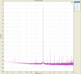
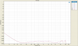
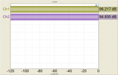
1. I took an AC coupled FFT measurement of the output of the PSU while connected to and powering the SE-SE amplifier. You can see the 120Hz fundamental caused by the rectifiers, and the subsequent harmonics at 240, 360, 480 and 600Hz. The negative rail is the purple trace and the positive rail is the greenish trace. The fundamental is about 20uV on the positive rail, and about 10uV on the negative rail. Overall, the supply is very quiet and well behaved up the measurement limit of 80kHz.
2. This is the same measurement as above, except only up to 20kHz and expressed in dBV.
3. This measurement simply shows the two rails on the AP scope.
Next up is the SE-SE amp!
Cheers,
Owen
Well, I finished measuring the SE-SE and the BAL-BAL version, as well as the PSU this evening. Tomorrow I'll measure the BAL-SE, then I'll be starting on the power amp.
In the meantime, I'll post what I've got so far. I'll toss them up here, and I'll compile them into a proper wiki and link to it from the main headphone amp wiki. In the wiki I'll discuss the significance of each measurement, and post up a more formal spec.
Let's start with the PSU:
1. I took an AC coupled FFT measurement of the output of the PSU while connected to and powering the SE-SE amplifier. You can see the 120Hz fundamental caused by the rectifiers, and the subsequent harmonics at 240, 360, 480 and 600Hz. The negative rail is the purple trace and the positive rail is the greenish trace. The fundamental is about 20uV on the positive rail, and about 10uV on the negative rail. Overall, the supply is very quiet and well behaved up the measurement limit of 80kHz.
2. This is the same measurement as above, except only up to 20kHz and expressed in dBV.
3. This measurement simply shows the two rails on the AP scope.
Next up is the SE-SE amp!
Cheers,
Owen
Attachments
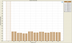
Next up we've got the SE-SE headphone amp. This little guy far exceeded my expectations, and those of you going with SE inputs and outputs will be glad to know that you're not really giving anything up in doing so!
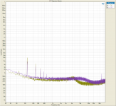
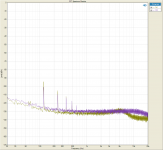
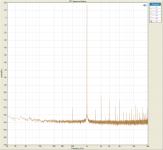
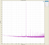
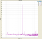
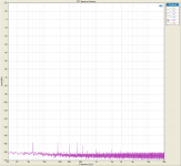
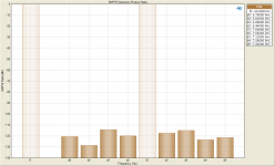
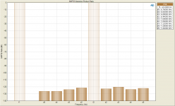
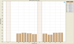
1. The first measurement is an FFT of the amplifier's output into a 50 ohm load with a 50 ohm load across the input which is disconnected from the AP. This basically eliminates the AP as a source of noise and shows the amplifiers true noise floor.
Thanks to the three layer board, the noise floor is about 10dB lower than the previous BAL-SE version, for a pretty stunning noise floor of between -160 and -164dBV. You can see the 60Hz noise and a few of the harmonics getting through, but they're all lower than -148dBV. This is the quietest amplifier I have ever measured.
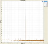
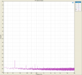
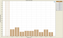
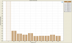
2. The next 6 measurements are all FFTs at various voltages driven into a 50 ohm load. There's 0V (AP plugged in but no signal), 100mV, 1V, 2V, 5V, and 7.2V which is the most the AP can put out single ended.
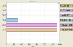
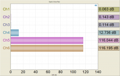
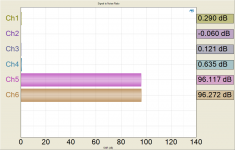
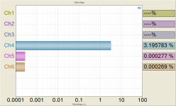
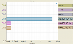
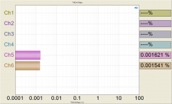
3. The last three measurements are calculated SNRs at 100mV, 1V and 7.2V. The channels of interest are 5 and 6, the other channels are not connected. These channels are used because they happen to be the best performing of the 8 channels.
More to come!
1. The first measurement is an FFT of the amplifier's output into a 50 ohm load with a 50 ohm load across the input which is disconnected from the AP. This basically eliminates the AP as a source of noise and shows the amplifiers true noise floor.
Thanks to the three layer board, the noise floor is about 10dB lower than the previous BAL-SE version, for a pretty stunning noise floor of between -160 and -164dBV. You can see the 60Hz noise and a few of the harmonics getting through, but they're all lower than -148dBV. This is the quietest amplifier I have ever measured.
2. The next 6 measurements are all FFTs at various voltages driven into a 50 ohm load. There's 0V (AP plugged in but no signal), 100mV, 1V, 2V, 5V, and 7.2V which is the most the AP can put out single ended.
3. The last three measurements are calculated SNRs at 100mV, 1V and 7.2V. The channels of interest are 5 and 6, the other channels are not connected. These channels are used because they happen to be the best performing of the 8 channels.
More to come!
Attachments
-
 Signal to Noise Ratio 7.2V 50R.png53 KB · Views: 172
 -
 Signal to Noise Ratio 1V 50R.png52.6 KB · Views: 185
 -
 Signal to Noise Ratio 100mV 50R.png52.5 KB · Views: 203
 -
 FFT Spectrum Monitor - 7.2V - 50R.png98.1 KB · Views: 168
 -
 FFT Spectrum Monitor - 5V - 50R.png98.5 KB · Views: 185
 -
 FFT Spectrum Monitor - 2V - 50R.png96.9 KB · Views: 205
 -
 FFT Spectrum Monitor - 1V - 50R.png96.9 KB · Views: 216
 -
 FFT Spectrum Monitor - 100mV - 50R.png95.3 KB · Views: 210
 -
 FFT Spectrum Monitor - 0V input.png93.1 KB · Views: 839
 -
 FFT Spectrum Monitor - 50R input.png92.6 KB · Views: 872
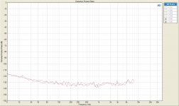
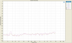
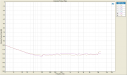
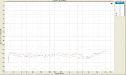
Continuing with the SE-SE amp we have:
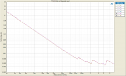
1, 2, 3 = Calculated THD+N ratios at three different drive levels, 100mV, 1V and 7.2V all into 50 ohms. Again, channels of interest are 5 and 6.
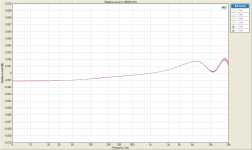
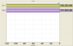
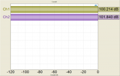
4 = Gain linearity which is basically showing that the gain remains perfectly linear regardless of output level. If you had an amplifier with a high output impedance, this would be all over the map. The Wire, however, doesn't flinch at all from the lowest to the highest output level.
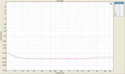
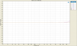
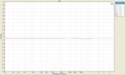
5 = Frequency response. Note the +/-1dB scale. The peak between 70 and 80kHz is the AP, not the amp.
6 = Frequency response zoomed in. This is probably one of my favorite measurements because it's almost funny how absurd it is. The 0.1% resistors mean that the channels match up better than 0.0001dB.
7 = THD+N ratio vs. Frequency - sweep
8 = THD+N ratio vs. Output Level - sweep
9 = THD ratio vs. Frequency - sweep
1, 2, 3 = Calculated THD+N ratios at three different drive levels, 100mV, 1V and 7.2V all into 50 ohms. Again, channels of interest are 5 and 6.
4 = Gain linearity which is basically showing that the gain remains perfectly linear regardless of output level. If you had an amplifier with a high output impedance, this would be all over the map. The Wire, however, doesn't flinch at all from the lowest to the highest output level.
5 = Frequency response. Note the +/-1dB scale. The peak between 70 and 80kHz is the AP, not the amp.
6 = Frequency response zoomed in. This is probably one of my favorite measurements because it's almost funny how absurd it is. The 0.1% resistors mean that the channels match up better than 0.0001dB.
7 = THD+N ratio vs. Frequency - sweep
8 = THD+N ratio vs. Output Level - sweep
9 = THD ratio vs. Frequency - sweep
Attachments
-
 THD+N Ratio 7.2V 50R.png67 KB · Views: 169
 -
 THD+N Ratio 1V 50R.png78.1 KB · Views: 182
 -
 THD+N Ratio 100mV 50R.png66.7 KB · Views: 210
 -
 THD Ratio Sweep 1V 50R.png76 KB · Views: 187
 -
 THD+N Ratio vs Measured Level 50R.png79.9 KB · Views: 181
 -
 THD+N Ratio Sweep 1V 50R.png70.2 KB · Views: 202
 -
 Relative Level 7.2V 50R - close up.png71.4 KB · Views: 200
 -
 Relative Level 7.2V 50R.png73.4 KB · Views: 742
 -
 Gain Linearity 50R.png70.1 KB · Views: 192
Last edited:
Next for the SE-SE amp we have:
1,2,3 = DFD Intermodulation distortion at three different drive levels.
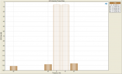
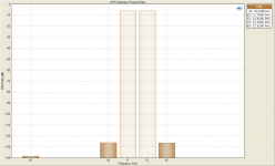
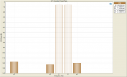
4,5,6 = SMPTE Intermodulation distortion at three different drive levels.
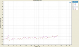
7,8,9 = Crosstalk at three different drive levels. As this is an SE output amp, this is where the BAL-BAL really pulls away. The SE amp hits the wall at about 100dB of channel separation, where the BAL-BAL, as you'll see later, does significantly better.
1,2,3 = DFD Intermodulation distortion at three different drive levels.
4,5,6 = SMPTE Intermodulation distortion at three different drive levels.
7,8,9 = Crosstalk at three different drive levels. As this is an SE output amp, this is where the BAL-BAL really pulls away. The SE amp hits the wall at about 100dB of channel separation, where the BAL-BAL, as you'll see later, does significantly better.
Attachments
-
 Crosstalk 7.2V 50R.png39.7 KB · Views: 135
 -
 Crosstalk 1V 50R.png39.6 KB · Views: 146
 -
 Crosstalk 100mV 50R.png39.3 KB · Views: 144
 -
 SMPTE Distortion Product Ratio 7.2V 50R.png52.4 KB · Views: 106
 -
 SMPTE Distortion Product Ratio 1V 50R.png51 KB · Views: 119
 -
 SMPTE Distortion Product Ratio 100mV 50R.png52 KB · Views: 118
 -
 DFD Distortion Product Ratio 7.2V 50R.png40.1 KB · Views: 110
 -
 DFD Distortion Product Ratio 1V 50R.png38.9 KB · Views: 128
 -
 DFD Distortion Product Ratio 100mV 50R.png40.2 KB · Views: 180
1,2,3,4,5 = sweeps showing distortion product ratio vs. frequency. Each harmonic is shown separately so you can see the character of each with respect to frequency.
6,7,8 = Distortion product ratio at three different drive levels.
6,7,8 = Distortion product ratio at three different drive levels.
Attachments
-
 Distortion Product Ratio - 6th 1V 50R.png76.5 KB · Views: 117
 -
 Distortion Product Ratio - 5th 1V 50R.png75.5 KB · Views: 116
 -
 Distortion Product Ratio - 4th 1V 50R.png76.8 KB · Views: 125
 -
 Distortion Product Ratio - 3rd 1V 50R.png72.9 KB · Views: 134
 -
 Distortion Product Ratio - 2nd 1V 50R.png75.9 KB · Views: 161
 -
 Distortion Product Ratio 100mV 50R.png48.6 KB · Views: 125
 -
 Distortion Product Ratio 1V 50R.png48.1 KB · Views: 119
 -
 Distortion Product Ratio 7.2V 50R.png48.9 KB · Views: 112
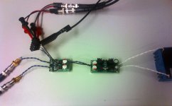
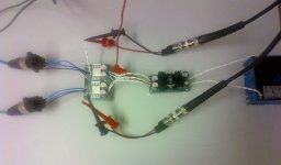
Overall, this amp measures incredibly well. I personally have never seen anything that has such low distortion that you're basically just measuring the AP's generators. The noise floor is so low that this amplifier will be completely silent into even the most sensitive IEM's, and yet you still get enough voltage and current drive to run the hungriest headphones out there. The very low output impedance means you get superb linearity, and a perfectly flat frequency response regardless of the load. I couldn't be happier with this little amp! Keep in mind that there are no tricks here... no batteries, no filters, no fancy chassis or shielding, just the supply and the amp running off a transformer.
I've attached a few shots of the test setup below.
BAL-BAL measurements to follow tomorrow.
Cheers,
Owen
I've attached a few shots of the test setup below.
BAL-BAL measurements to follow tomorrow.
Cheers,
Owen
Attachments

- Home
- Amplifiers
- Headphone Systems
- "The Wire" Ultra-High Performance Headphone Amplifier - PCB's