ONE VERY IMPORTANT NOTE TO ALL BUILDERS:
Please make sure to set both pots on the PSU to minimum (0R) before powering up the supply. If they are set to maximum, you risk putting upwards 17 volts on the caps at the output, and it may be enough to damage some polymer caps. I built a kit here before I shipped everything to ensure I had all the parts, and this was the only problem I had.
Always power the PSU up first with no load, and make the adjustments before connecting to the amplifier PCB. Those IC's are quite dear, and it would be a shame to damage anything by hooking the supply up incorrectly.
Best of luck to all with the build!
Cheers,
Owen
OPA1632(THS4131) is a fully-differential SINGLE package amplifier. TI licensed the "SuperSymmetry" patent from Mr. Nelson Pass for this series of OP amps.
texas-instruments-licenses-pass-patent
LME49990 is a very nice OP amp but, in this application, I like a fully-differential amplifier on one silicon die better than two OP amps in two different packages.
texas-instruments-licenses-pass-patent
LME49990 is a very nice OP amp but, in this application, I like a fully-differential amplifier on one silicon die better than two OP amps in two different packages.
ONE VERY IMPORTANT NOTE TO ALL BUILDERS:
Please make sure to set both pots on the PSU to minimum (0R) before powering up the supply. If they are set to maximum, you risk putting upwards 17 volts on the caps at the output, and it may be enough to damage some polymer caps.
Just to clarify, minimum means all the way counter clockwise?
-N
yes the OPA1632 is a very nice chip, one of my favorites and sounds very very well, but wouldnt opc just be duplicating the IVY from buffalo32 plus added buffer if he did that? seems like thats all been done before more than once. I have a very nice balanced headamp using these chips on the output of my portable buffalo II, basically an IV stage with gain. uses the wide soic8 with heatsink pad on the underside.
NBROCK, if you have mounted it correctly yes I think fully counter clockwise, but why not just use the DMM to check?
NBROCK, if you have mounted it correctly yes I think fully counter clockwise, but why not just use the DMM to check?
Hi opc,
You have made a fine headphone amplifiers using using some of the best op-amps available.
However there are a couple of mistakes in the interpretation of your measurements that I would like to point out.
Looking at the first FFT spectrum shows that the "grass" at the bottom of the graph lies around -145dB. This does not imply that the SNR is 145dB. The level of the "grass" is dependent on the FFT size that the analyzer uses, and the averaging function of a long FFT will move the "grass" down since the noise is white. This is a good thing though as it makes it easy to read the distortion products since they now stand out from the noisefloor.
A better way to calculate SNR is from the last THD+N vs Level graph in post 3. At the left part of the curve where it slopes evenly down, the THD+N is dominated by noise. At a point on the curve, you can read the THD+N and calculate SNR from it like so: At 10mV the THD+N is approx 0.02%. 10mV*0.02% = 0.01V*0.0002 = 2e-6V. 20*log10(2e-6) = -114dBV which is the noise level. Since the circuit clips at 10Vrms the dynamic range (or SNR for a full scale sinewave) is -114-20 = -134dB. Still pretty good.
The second thing I want to point out is that none of the graphs in post 107 show the distortion products for a 10kHz signal. In order to see that you would need a larger measurement bandwidth than 20kHz, preferably large enough to include up to the 7th harmonic.
Looking forward to seeing the results of the builds coming together!
- ojg
You have made a fine headphone amplifiers using using some of the best op-amps available.
However there are a couple of mistakes in the interpretation of your measurements that I would like to point out.
Vanishingly low THD+N and IMD levels, incredibly flat FR, no phase shift in the audible band, and an astonishing 145dB SNR.
Looking at the first FFT spectrum shows that the "grass" at the bottom of the graph lies around -145dB. This does not imply that the SNR is 145dB. The level of the "grass" is dependent on the FFT size that the analyzer uses, and the averaging function of a long FFT will move the "grass" down since the noise is white. This is a good thing though as it makes it easy to read the distortion products since they now stand out from the noisefloor.
A better way to calculate SNR is from the last THD+N vs Level graph in post 3. At the left part of the curve where it slopes evenly down, the THD+N is dominated by noise. At a point on the curve, you can read the THD+N and calculate SNR from it like so: At 10mV the THD+N is approx 0.02%. 10mV*0.02% = 0.01V*0.0002 = 2e-6V. 20*log10(2e-6) = -114dBV which is the noise level. Since the circuit clips at 10Vrms the dynamic range (or SNR for a full scale sinewave) is -114-20 = -134dB. Still pretty good.
The second thing I want to point out is that none of the graphs in post 107 show the distortion products for a 10kHz signal. In order to see that you would need a larger measurement bandwidth than 20kHz, preferably large enough to include up to the 7th harmonic.
Looking forward to seeing the results of the builds coming together!
- ojg
Hi Guys,
Glad to hear the boards are slowly arriving! Keep the updates coming as they arrive.
multisync:
Great to hear! Thanks very much for the feedback. What are you using for a source?
dggs:
You've definitely got my attention... I should have read a little farther down the datasheet. I assumed from the first page that it was just a dual op-amp with a "balanced" label stuck on it, but it looks like there's a little more to it than that.
I'll look into it and get back to you. It just might be the way to go.
chris719:
Shipping with tracking via Canada Post requires insurance, and it costs a fortune. An tracked package to Australia (50 grams, 10cm x 14cm x 1cm) for example was going to be $64.
For that reason, nothing went out with tracking, but I have yet to run into any issues with shipping. If someone still doesn't have a package two weeks from now, then I'll look into it.
ojg:
You're absolutely correct, I should have used the term "noise floor" to describe the -145dB rating. The actual SNR as measured on the AP is 136dB, pretty much exactly what you worked out.
For the record, the FFTs were done at 64k and averaged over 5 samples.
Again, you are correct. I set the measurement BW to 90kHz but didn't think to adjust the graphs. What was posted in 107 is a little meaningless when you can't see the second harmonic!
I'll re-do those measurements and post the results. Thanks for catching that.
Cheers,
Owen
Glad to hear the boards are slowly arriving! Keep the updates coming as they arrive.
multisync:
Great to hear! Thanks very much for the feedback. What are you using for a source?
dggs:
You've definitely got my attention... I should have read a little farther down the datasheet. I assumed from the first page that it was just a dual op-amp with a "balanced" label stuck on it, but it looks like there's a little more to it than that.
I'll look into it and get back to you. It just might be the way to go.
chris719:
Shipping with tracking via Canada Post requires insurance, and it costs a fortune. An tracked package to Australia (50 grams, 10cm x 14cm x 1cm) for example was going to be $64.
For that reason, nothing went out with tracking, but I have yet to run into any issues with shipping. If someone still doesn't have a package two weeks from now, then I'll look into it.
ojg:
Looking at the first FFT spectrum shows that the "grass" at the bottom of the graph lies around -145dB. This does not imply that the SNR is 145dB. The level of the "grass" is dependent on the FFT size that the analyzer uses, and the averaging function of a long FFT will move the "grass" down since the noise is white. This is a good thing though as it makes it easy to read the distortion products since they now stand out from the noisefloor.
You're absolutely correct, I should have used the term "noise floor" to describe the -145dB rating. The actual SNR as measured on the AP is 136dB, pretty much exactly what you worked out.
For the record, the FFTs were done at 64k and averaged over 5 samples.
The second thing I want to point out is that none of the graphs in post 107 show the distortion products for a 10kHz signal. In order to see that you would need a larger measurement bandwidth than 20kHz, preferably large enough to include up to the 7th harmonic.
Again, you are correct. I set the measurement BW to 90kHz but didn't think to adjust the graphs. What was posted in 107 is a little meaningless when you can't see the second harmonic!
I'll re-do those measurements and post the results. Thanks for catching that.
Cheers,
Owen
i ve finally fired it up and it s now playing music. i did have bad solder joints and had to find them.
bass is pretty much the most realistic i heard, from memory and detail is stellar too. for sure worth the build. i have yet to compare it to the B22 and DAO. they are all pretty good though...
thanks to Owen for all the time he spent on this and his generosity.
bass is pretty much the most realistic i heard, from memory and detail is stellar too. for sure worth the build. i have yet to compare it to the B22 and DAO. they are all pretty good though...
thanks to Owen for all the time he spent on this and his generosity.
I'm plowing through the whole thread in reverse to get up to speed... ")
Another option - the LME49724 is a fully differential op-amp that is part of that same high end audio LME49xxx series - very low noise and distortion.
LME49724 - High Performance, High Fidelity, Fully-Differential Audio Operational Amplifier
The part is surface mount. $2.27 each and in stock at Arrow.
If a new board were to have two LME49600s per channel, it would be particularly cool if it could be optionally wired to have the two in parallel (for single ended use) rather than bridged. That would give the board an optional dual-use. I've read some posts claiming that two in parallel sound even better. (Even) lower output impedance, I would think. The LME49600s should be able to be directly paralleled given the emitter resistors in the functional block diagram. Wiring BUF634s in parallel was also apparently pretty common.
Another thought. If the power supply board ever gets re-spun an idea would be to add (the rest of) Jung Super-Regulator parts after those LM317/LM337s to produce some extremely well regulated rails to go with that high end audio:
Op-Amp Based Linear Regulators
But instead of the AD797/AD825 use the LME49990. The part is so similar to the AD797 it should work. Wouldn't take up that much additional board space, although the additional drop across the BJT pass would probably require a slightly higher input voltage.
-agdr
LME49990 is a very nice OP amp but, in this application, I like a fully-differential amplifier on one silicon die better than two OP amps in two different packages.
Another option - the LME49724 is a fully differential op-amp that is part of that same high end audio LME49xxx series - very low noise and distortion.
LME49724 - High Performance, High Fidelity, Fully-Differential Audio Operational Amplifier
The part is surface mount. $2.27 each and in stock at Arrow.
If a new board were to have two LME49600s per channel, it would be particularly cool if it could be optionally wired to have the two in parallel (for single ended use) rather than bridged. That would give the board an optional dual-use. I've read some posts claiming that two in parallel sound even better. (Even) lower output impedance, I would think. The LME49600s should be able to be directly paralleled given the emitter resistors in the functional block diagram. Wiring BUF634s in parallel was also apparently pretty common.
Another thought. If the power supply board ever gets re-spun an idea would be to add (the rest of) Jung Super-Regulator parts after those LM317/LM337s to produce some extremely well regulated rails to go with that high end audio:
Op-Amp Based Linear Regulators
But instead of the AD797/AD825 use the LME49990.
The part is so similar to the AD797 it should work. Wouldn't take up that much additional board space, although the additional drop across the BJT pass would probably require a slightly higher input voltage.-agdr
Last edited:
Received my board and parts yesterday and put together the amp board today. I currently have it running with a +/-15V Elpac WM071, but even with this regulated wall wart it's still by far the cleanest and most detailed amp I've heard. It's running from an E-MU 1616M (balanced) into Sennheiser HD600s, and wow, I have to agree with everyone else about the bass. This thing's great! Thanks Owen!
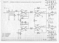
Hi OPC, and everyone interested.
My suggestion for Your next project with balanced output:
Here You can see my idea for a balanced headphone amplifier.
Instead of a “old!!?” LME49710 is useful to use the new LME49990 or another ultra Hi-performances operational amplifier as pleasure.
I think the “Super Symmetry” topology is better than a conventional balanced output stage since the S.S. have an inherent crossed distortion cancellation that push the output stage to a very low distortion performances . Moreover with a little amount of components combined in an very elegant way ,as the SuSy is, is possible to realize a super Hi-performance headphone amplifier that can drive any kind of dynamic headphone at any level with negligible level of distortion.
As Mr. Pass say ,for the best performances is very important that the resistors and the traces placed in the crucial positions for the mutual cancellation action should be matched at least 0,1 % or better. So is also important the perfect symmetry and equal length of the physical traces placed in the P.C.B.
For other info about SuSy applied to the Current Feedback chips check the phrase “Monolytic Supersimmetry” in the Nelson Pass forum.
Due to low power supply rejection ratio of the current feedback operational amplifiers is probably better to use a “Jung Super Regulator as power supply circuit instead of conventional LM317/337 regulators.
Since the current feedback chip employed has a relative big (for a headphone amplifier) DC offset , I suspect that a offset ,manual or servo, circuit control is needed.
Maybe the crossed distortion cancellation topology can null also DC offset?
Best Regards
Semola.
Attachments
- Home
- Amplifiers
- Headphone Systems
- "The Wire" Ultra-High Performance Headphone Amplifier - PCB's