Hi Paul,
Looks like your question has been missed
I haven't had time to check it in detail, but worth checking with the ivy iii manual for cod and opa1632 as I/V.
Thanks, not a problem
")
Checked over the COD and IVY III spec's, and its pretty close to the I/V, filter and Differential to SE/Buffer stage shown in the PCM1794A datasheet.
The main difference is in the second stage, which is used to set 2VRMS or 4VRMS output level. The IVY's second stage is BAL-BAL then SE, the datasheet is BAL - SE, so the amount of applied gain is different.
Using a 750R feedback resistor with 'The Wire' BAL-BAL will give me 2VRMS per + and - output.
Again, this is where my understanding on differential output falls down... is the above 2VRMS balanced output into balanced headphones just 2VRMS, or is it 4VRMS as both + and - are outputting 2VRMS. Or, does it only become 4VRMS if you convert from balanced to single ended?
Thanks once again
Paul.
Damn, I spent so much time looking at the schematic and didn't notice those things... But still, the fact that there's a short between +12 and GND just can't be right. I've started cutting into the PCB to cut any possible shorts but that isn't helping either. I think I'll just order a new PCB and start over. A blown regulator (although I wouldn't know what blew it) might also be at fault..
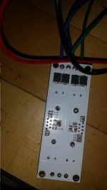
It's me again. Since I have 4 boards and the respective parts to populate them (and just ordered 2 more) I was able to finish another PSU, and to my dismay it displays the same behavior as the first one - 1V across the negative side, 20 across the positive one. I'm starting to think I'm doing something fundamentally wrong, so I've attached a picture of my soldered board below. I was extremely careful this time and I'm sure I didn't burn anything. The transformer I'm using is an AN-0215 and it has proper dual secondaries according to the datasheet. Also, the resistances across the rails are very different again - on the positive rail, it's measurable but something's weird:
No matter what range of resistance I select on my MM, it'll tell me it's either 3.22 or 0.322 of the corresponding unit (so with the 2MOhm range selected, it'll tell me it's 0.322 MOhm while the 20MOhm range tells me it's 3.22MOhm). On the negative side, it's just infinity no matter what I set the MM to. To my understanding, the resistance across C28/54 and across C93/85 should be the same since the circuit "in between" looks exactly the same on both sides, no?
Also, the unregulated DC voltage is still at a perfectly fine 20V after the bridge rectifiers, and neither of the regulators is getting hot.
I really don't know what to do now... Can anyone offer any guidance? I can provide any measurements and/or pictures you might need to diagnose the problem.

Last edited:
Sorry, the edit limit just expired again...It's me again. Since I have 4 boards and the respective parts to populate them (and just ordered 2 more) I was able to finish another PSU, and to my dismay it displays the same behavior as the first one - 1V across the negative side, 20 across the positive one. I'm starting to think I'm doing something fundamentally wrong, so I've attached a picture of my soldered board below. I was extremely careful this time and I'm sure I didn't burn anything. The transformer I'm using is an AN-0215 and it has proper dual secondaries according to the datasheet. Also, the resistances across the rails are very different again - on the positive rail, it's measurable but something's weird:
No matter what range of resistance I select on my MM, it'll tell me it's either 3.22 or 0.322 of the corresponding unit (so with the 2MOhm range selected, it'll tell me it's 0.322 MOhm while the 20MOhm range tells me it's 3.22MOhm). On the negative side, it's just infinity no matter what I set the MM to. To my understanding, the resistance across C28/54 and across C93/85 should be the same since the circuit "in between" looks exactly the same on both sides, no?
Also, the unregulated DC voltage is still at a perfectly fine 20V after the bridge rectifiers, and neither of the regulators is getting hot.
I really don't know what to do now... Can anyone offer any guidance? I can provide any measurements and/or pictures you might need to diagnose the problem.
I just tried only connecting one side of the PSU to 15V AC, and the results are the same - I get 20V from the positive side, and 0.6-1V from the negative one separately.
Hi butizzle,
Sorry to hear you're having so many problems.
The picture you posted of the board looks pretty good, so it's not looking like it's a problem with soldering.
What are you doing for isolation between the regulators and the heatsinks? Are you using the correct non-conductive pads and fully isolated screws? When you measure the resistance from the tab of the regulator to the soldered pins on the heatsink, do you see an open circuit?
If that's not the problem, then there isn't much more I can think of. It's especially strange that you've had the same problem twice now. If you have the proper 20V across each filter cap heading into the regs (on the unregulated side) then there are only a small handful of things left that could be causing the problem.
Let me know about the isolation and we can go from there.
Cheers,
Owen
Hi butizzle,
Sorry to hear you're having so many problems.
The picture you posted of the board looks pretty good, so it's not looking like it's a problem with soldering.
What are you doing for isolation between the regulators and the heatsinks? Are you using the correct non-conductive pads and fully isolated screws? When you measure the resistance from the tab of the regulator to the soldered pins on the heatsink, do you see an open circuit?
If that's not the problem, then there isn't much more I can think of. It's especially strange that you've had the same problem twice now. If you have the proper 20V across each filter cap heading into the regs (on the unregulated side) then there are only a small handful of things left that could be causing the problem.
Let me know about the isolation and we can go from there.
Cheers,
Owen
Thanks for the quick response, Owen!
I'm using two of those ugly grey isolating thermal pads (I think they're silicone, but I'm not sure - on the last build I used transparent mica pads) together with a rubber washer each and it seems to be working: On the negative side, the tab of the regulator and the heatsink are shorted, on the positive side, there is an open circuit. This seems to me to be correct according to the regulator's datasheet, which states that the tab is internally shorted to the ground pin (which is connected to GND e.g. the heatsink solder pins on the negative side). The positive reg's tab is shorted to +15V, as expected.
I've also checked the connections between all the parts and it all seems correct, but the resistances I measure are just plain impossible. On the positive rail, the rail-ground resistance starts at 15 MOhm - much too high considering there's only a 1.24MOhm+133kOhm in series in between - and then starts falling (shouldn't it rise, if anything, because as capacitances across the rail get charged, they "suck" up less current?) for some reason. I wasn't patient enough to wait until it stopped moving, so I can't tell you where it ends up. On the negative side, it's stable at 3MOhm - also way too much. I study electrical engineering and so you can imagine that I am extremely flabbergasted right now as this seems to violate Ohm's law if my readings are correct. Which means they either aren't - that would be weird as this DMM has always worked reliably for me - or I'm missing something, which I'm guessing is the case. I just don't know where the problem lies. I don't think it's the regulators either as I always took care to touch a grounded point before I touched them and was quick with soldering the pins.
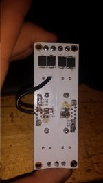
I should also mention that after making my previous board look like pic related, I'm getting exactly 12V DC on one rail (I do believe it's the one I mutilated, but I'm not 100% positive) - the other one's still screwing up. This was of course measured with C17 and C55 in place; I removed them and used them in the new build because I noticed that I wouldn't have enough of those caps to fill all of my boards with the two I ordered from you a few days ago.
Thanks a lot for taking the time to help me out,
Georg
Last edited:
Hi Georg,
Too bad it's not the low hanging fruit of the isolators...
Looks like you've got everything in order there.
Doing any sort of in-circuit resistance measurement is not going to provide you with anything very meaningful unless you have an open circuit, a short, or a component which is disconnected on one end. There is just too much going on to take a measurement across the output and GND to expect to get anything reasonable. You'll be charging the caps, and there could be internal protection diodes on the reg that will shunt voltage on the output back to the input, adding those caps into the equation.
Let me think it over for a little bit... maybe I'll come up with something. I have never seen this particular fault before, and I cannot think of anything that could possibly be causing it. Even if all the ceramic caps were left out, the circuit should still be working perfectly (with the exception of C17/C55).
That leaves R29, R30, R52 and R55 as pretty much the only other possible issues.
As a side note, have you checked the polarity of the voltage on the caps at the input of the regulators? Do you have all the rectifier diodes in correctly?
If you have the correct polarity 20V unregulted voltage on the caps before the regs, then it has to be either the regs or the set resistors.
Cheers,
Owen
Hi Georg,
Too bad it's not the low hanging fruit of the isolators...
Looks like you've got everything in order there.
Doing any sort of in-circuit resistance measurement is not going to provide you with anything very meaningful unless you have an open circuit, a short, or a component which is disconnected on one end. There is just too much going on to take a measurement across the output and GND to expect to get anything reasonable. You'll be charging the caps, and there could be internal protection diodes on the reg that will shunt voltage on the output back to the input, adding those caps into the equation.
Let me think it over for a little bit... maybe I'll come up with something. I have never seen this particular fault before, and I cannot think of anything that could possibly be causing it. Even if all the ceramic caps were left out, the circuit should still be working perfectly (with the exception of C17/C55).
That leaves R29, R30, R52 and R55 as pretty much the only other possible issues.
As a side note, have you checked the polarity of the voltage on the caps at the input of the regulators? Do you have all the rectifier diodes in correctly?
If you have the correct polarity 20V unregulted voltage on the caps before the regs, then it has to be either the regs or the set resistors.
Cheers,
Owen
Hi Owen,
The unregulated voltage is (following the electrolytics' polarisation) correct as far as I can see.
Also, I'm now getting 0V instead of 20V on the positive rail - my guess is that the regulator(s) are/is toasted because I accidentally set off a short while I was trying to measure something from the regulator pins shortly after pulling the plug on the transformer and apparently some of the caps were still charged... Either way, now it's 0.0V on one side of the output and 0.6V or so on the other.
Also, I forgot to post the pic of the molested PCB of the previous build (that gave 12V at least on one side) in my last reply:

Last edited:
The image needs cropping & reducing as it blows out the margins in our browsers
Interestingly, when i was composing this, i could see the image, but Greatly reduced !
It's linked from here -https://i.imgur.com/yb02Hvs.jpg so you have to allow Requests in your browser to view it
EDIT
Since i posted the image now easily fits in the post ?
Interestingly, when i was composing this, i could see the image, but Greatly reduced !
It's linked from here -https://i.imgur.com/yb02Hvs.jpg so you have to allow Requests in your browser to view it
EDIT
Since i posted the image now easily fits in the post ?
1k & 110r will give slightly less noise in return for running with a lot of power. That power must be dissipated and requires many more small components or one very large component. The extra size could introduce more noise/interference.
The 10k & 1k1 will be very slightly noisier, and power dissipation stills needs attention.
100k and 11k will be noisier still, not have any dissipation concerns, even using 1/8th W devices. And allow very low value high quality capacitors.
There is no "best"
The 10k & 1k1 will be very slightly noisier, and power dissipation stills needs attention.
100k and 11k will be noisier still, not have any dissipation concerns, even using 1/8th W devices. And allow very low value high quality capacitors.
There is no "best"
Some, including me, suggest that the Pmax of the feedback resistors be at least 10 times the maximum dissipation when amplifier is at full audio output voltage.
eg. 100W into 8r0 amplifier is equivalent to 28.3Vac.
A 10k+1k1 will pass ~2.55mAac at that maximum output voltage.
If the amplifier has a terrible transient power overhead, just ignore that useless and inflated figure.
2.55mA through 10k is 65mW.
Use a resistor that has >650mW of Pmax.
SMD does not get near that. Three 1/4W 805 will do the job.
You could use three 30k in parallel for a 10k 3/4W equivalent. But this exposes each feedback resistor to full output voltage of 40Vpk. Not good practice, particularly with tiny SMD.
Instead use three 3k3 in series for a 9k9 3/4W equivalent.
Fortunately you are asking about a headphone amplifier.
A 10k 1/4W resistor dissipates ~25mW when 15.8Vac is applied. You should be well inside that.
i.e. adopt a feedback pair that gets close to the 10% of Pmax for least noise in the headphones and still leaves the feedback resistors cold at normal operating voltages.
BTW,
does your headphone amplifier NEED 10times gain?
Last edited:
Andrew: I've attached the pictures to this post - I'd strongly suggest disabling any URL filters in AVG though, they're pretty much useless and if imgur is on there, I really don't know what they were thinking.
Anyway, I have now removed the regulator on the positive rail and the resistance across R29 (which is 1.24 MOhms) is STILL 3.3 MOhms. Without the regulator in there, there should be nothing to complicate matters and give a higher resistance, no? I'm really stumped here.
Anyway, I have now removed the regulator on the positive rail and the resistance across R29 (which is 1.24 MOhms) is STILL 3.3 MOhms. Without the regulator in there, there should be nothing to complicate matters and give a higher resistance, no? I'm really stumped here.
Attachments
Last edited:
Seems I'm another one with problems on the new PSU design.
Everything is soldered correcty, no shorts anywhere, regulator pass diode test in every pin and the tab, which has a different potencial in each of them (15V vs 0V) as it should.
But the negative rail works and the positive one doesn't.
Strangely, my DMM seems unable to see the real resistance of the SMD resistors, with values going up and down with some of them (the DMM has no problem). This is outside the circuit. So, how fragile are SMD resistors to heat and handling? It's the first time I've used them.
The amp itself looks great and everything seems alright, but I can't turn it on because it lacks the PSU as of now...
I've received my PSU PCBs about 4 weeks ago.
They work fine; I don't think it is a layout problem.
The hardest thing for me to do was soldering the diodes correctly to the ground layer.
It was easier to do with FLUX and more heat.
@patchoncas
sorry for misspelling your name in one of my recent posts.
They work fine; I don't think it is a layout problem.
The hardest thing for me to do was soldering the diodes correctly to the ground layer.
It was easier to do with FLUX and more heat.
@patchoncas
sorry for misspelling your name in one of my recent posts.
Last edited:
@patchoncas
sorry for misspelling your name in one of my recent posts.
No, it's definetly not a layout problem, it's some faulty component somewhere. But it isn't the regs, so that leaves what, the resistors? All the caps charge as they should.
And I didn't even see the misspell, that was hilarious.
- Home
- Amplifiers
- Headphone Systems
- "The Wire" Ultra-High Performance Headphone Amplifier - PCB's