picovolt, you don't have to switch to SE to have a balanced volume control. If you have already googled balanced volume control, there is one method you will see that you have to put 2 resistors in series with the inputs of the op amps and then a volume control in between the inputs. You don't have to mod the boards, just add the parts externally to the board.
Thanks. I understand the circuit part of adding the balanced control; my confusion was (is?) with figuring out the correct values for ri and rf to get a gain increase. From rereading posts I'm now thinking that the input impedance will be 5k ( with a 10k ri and 10k attenuator), but that the gain is still figured by rf/ri, so for a gain of 3, I want 30k for rf. I'm waiting for my next mouser order to come in, and will know if this is all correct with a few weeks. I ordered several values of resistors, so can always experiment that way.
Many do not agree with you.picovolt, you don't have to switch to SE to have a balanced volume control. If you have already googled balanced volume control, there is one method you will see that you have to put 2 resistors in series with the inputs of the op amps and then a volume control in between the inputs. You don't have to mod the boards, just add the parts externally to the board.
D.Self discusses this at length.
Putzeys rejects it specifically in the links I gave above.
Hi Andrew,
thanks for your links above.
Do you also have a source for Self's discussion?
Cheers,
Sebastian.
thanks for your links above.
D.Self discusses this at length.
Do you also have a source for Self's discussion?
Cheers,
Sebastian.
It's in some of his web pages, or link to his numerous articles.
It is in his early editions of the power amp design book.
It's also in his active crossover book.
I think it may be in his preamp book, but that one I don't have.
I see that Pico has not acknowledged the effort I went to, to find those links.
It is in his early editions of the power amp design book.
It's also in his active crossover book.
I think it may be in his preamp book, but that one I don't have.
I see that Pico has not acknowledged the effort I went to, to find those links.
H-pads attenuate the differential-mode component without affecting the common-mode component. At low volume settings, effective CMRR of the whole system may even become negative. H pads are out. A two-gang potentiometer will convert CM to DM unless matching is phenomenal. Other than that, CM impedance is directly determined by DM impedance.
For noise and distortion reasons you'd like a low-resistance pot; for CMRR reasons you'd like high resistance. This is going nowhere either. It turns out that there is no acceptable method of constructing a balanced passive volume controller. In fact, there is no sensible way to arrange a potentiometer in a differential fashion.
Last edited:
Hi Owen,
When will we be able to order the new flavors of NTD1? Do you have a sign up sheet for them?
Thanks
Do
Its on the same sign up sheet.
NTD1 signup
I want one too.
")
I want to try different output stages for my 9018 dac.
It is in his early editions of the power amp design book.
Thanks. I'll take a look into my copy.
My current question (open to everyone, of course) is this:
I'm considering fully-differential op-amps (input and output, i.e. LME49724, THS413x, OPA1632, etc.).
As has been discussed, the H-pad (differential shunt) doesn't attenuate common-mode signals.
But won't an instrumentation stage (i.e. as suggested in Bruno's G word demo, just with differential output) already have taken care of that?
In other words: How much common-mode distortion is there at the output of a proper instrumentation amp, considering that they typically have CMMR in the order of 100dB or better?
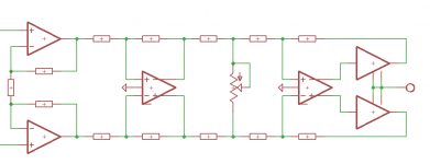
I was considering such an instrumentation amp with a shunting volume pot in front of a BAL-BAL Wire...
I'm pretty sure I could leave out a couple of components, but the general idea is this:
Attachments
Last edited:
I see that Pico has not acknowledged the effort I went to, to find those links.
Andrew, thank you! Today is the first day I've had time to look through the links etc., due to a crazy project at work. I thought I understood adding a volume control, but it is more involved than I realized, and the links do a great job of explaining the issues. My original plan was to use a stepped attenuator with 0.1% resistors in it. I wonder if this would track well enough to keep the CMRR a non issue?
If you need balanced to minimise interference, then the variation in switching resistances will limit the attenuation achievable and is likely to be variable.
If balanced is just for the sake of maintaining a good signal where interference is not a big issue, then switching resistances may not matter much.
If balanced is just for the sake of maintaining a good signal where interference is not a big issue, then switching resistances may not matter much.
Is there anyway I can get the Gerber files for "the wire AMP class A A/B power amp"? If I can get the gerber files and a Parts list I can just order PCBs myself and then build this AMP. If anyone can help I would greatly appreciate it. I understand that OPC probably doesn't have time for this anymore.
If you need balanced to minimise interference, then the variation in switching resistances will limit the attenuation achievable and is likely to be variable.
If balanced is just for the sake of maintaining a good signal where interference is not a big issue, then switching resistances may not matter much.
Interference is really not an issue for me in this application, but the efficiency of using a bleed appeals to me. I've been looking more and more at the "fig17b" circuit (resistors in front of pot used as VR to bleed phases together) and wonder if with these resistors in circuit, do they replace in input resistors in the bal bal wire? Having 5k resistors there, and then 10k resistors as IR right after them (or more correctly, right after the VR) seems redundant, to my admittedly ignorant understanding. It also completely confuses me as regards to figuring out what the ratio of IR / FR becomes, in terms of adjusting gain.
Andrew, you keep popping up as a contributor the more I look into this, so any help would be appreciated.
Some specifics: (too late to just edit). Source is a legato IV, with output impedance of 150 ohms. Bal bal has either a 1k ( if no volume control is in circuit) or 10k (per Owens suggestions) input impedance if a volume control is used. If the legato needs to see a load before the phase bleed pot, then it seems like 3k would be sufficient in terms of a 20x rule of thumb. If I have a 10 k IR, and use a 10k pot, along with 3k lead in resistors, is the total input resistance 5k (IV res and pot) +3k +3k = 11k? (This is from a pass amp thread from 2013) and gain (not the amp gain yet) would be 5k/11k = .46? This seems like a harsh waste of signal.
Last edited:
Just put my name on the spreadsheet, then I realized that this thread is from 2013. Is there any progress here?
Absolutely. Got my boards a few weeks ago. Not a long wait, and even if it had been, well worth it.
Some specifics: (too late to just edit). Source is a legato IV, with output impedance of 150 ohms. Bal bal has either a 1k ( if no volume control is in circuit) or 10k (per Owens suggestions) input impedance if a volume control is used. If the legato needs to see a load before the phase bleed pot, then it seems like 3k would be sufficient in terms of a 20x rule of thumb. If I have a 10 k IR, and use a 10k pot, along with 3k lead in resistors, is the total input resistance 5k (IV res and pot) +3k +3k = 11k? (This is from a pass amp thread from 2013) and gain (not the amp gain yet) would be 5k/11k = .46? This seems like a harsh waste of signal.
I am curious about your experience of using the TPA Legato IV with the Bal/Bal Wire amp. There is common mode DC bias of the Legato's balanced outputs relative to the ground. Did you run into issues with this DC bias? How did you wire the Legato's balanced outputs to the Wire's inputs - did you connect the grounds between the Legato and the Wire?
I have both the TPA Ivy III and Legato 3.1 IV stage and am currently using the IVY with the Wire but would like to try the Legato as well. I use the digital volume control of the Buffalo II DAC so I feed the IVY's output directly to the Wire without a volume pot in between.
Thanks!
^^ Hi MWL,
Have you measured your DC bias out from the Legato? I’ve been able to keep mine well below 1mV, and it has never been an issue with the balanced speaker amps I use. The adjustment is pretty easy. In any case, I have not attached ground at either the legato outs or the BAL BAL inputs. I’m also using the digital volume control, though I plan to add in a volume at some point, since I may also use this with a NOS dac (if I finally start the build...)
I just got the BAL BAL hooked into the Legato last night for the first time (was waiting for a balanced headphone cable) and there is no noise—it’s a dead quiet back ground. I’m not sure if the ground connection would help with a DC problem anyway (although it could help with longer cable runs, etc.). I think if you have a DC issue, you’ll need to put a capacitor in—but first see how low you can get it adjusted.
Hi guys,
my 49830-boards run well, but I have a problem with the signal...
When I short the signal-in (+-) the amp is deadly quiet, but when I connect any kind of source (smartphone, laptop, cd-player, standalone soundcard) there is a quiet hum audible (like dzdzdzdz...). When I open the signal-in the hum is a little louder.
I checked any grounding possibilities, tried only one and two amps per power supply, one power supply per amp (including the LME49830) and a separate ps, but always with the same result.
Does anybody have any idea, what I can try?
I tried a ps consisting only of capacitors and also a stabilized ps, no differences. In same environment other amps are not having this problems...
Last edited:
^^ Hi MWL,
Have you measured your DC bias out from the Legato? I’ve been able to keep mine well below 1mV, and it has never been an issue with the balanced speaker amps I use. The adjustment is pretty easy. In any case, I have not attached ground at either the legato outs or the BAL BAL inputs. I’m also using the digital volume control, though I plan to add in a volume at some point, since I may also use this with a NOS dac (if I finally start the build...)
I just got the BAL BAL hooked into the Legato last night for the first time (was waiting for a balanced headphone cable) and there is no noise—it’s a dead quiet back ground. I’m not sure if the ground connection would help with a DC problem anyway (although it could help with longer cable runs, etc.). I think if you have a DC issue, you’ll need to put a capacitor in—but first see how low you can get it adjusted.
Thanks for the quick reply Picovolt.
I suspect your measurment of 1mv DC offset of the Legato is between the +/- differential outputs. I have no problem nullifying the DC offset of the differential outputs with my Legato either. The common mode DC I am refering to is measured between either one of the differential outputs to the ground, it is typically around 6V or 7V. This is designed into the Legato III. Here is a thread refering to this matter: http://www.diyaudio.com/forums/twis...ommon-mode-dc-you-how-do-you-choose-deal.html
In any case, seems like you did not have problem using the Legato's balanced outputs with the full balanced Wire when not connecting the ground which is good to know. I have tried the same thing with the same result some time ago if I recall correctly. But I was wondering if there is any ill effect that can not be "heard" since I do not have any instrument for measurments other than a digital multimeter.
Hi All,
I am interested in the PCBs for the Wire but I can't find the correct place or link to order.
Are they still available? Can somebody address me?
Thanks for your help and Regards,
Enrico
Go to the very first post in this thread and there is a link to a spreadsheet to place orders. Owen is still shipping orders and replenishing stock when it runs low. Give him some time, after you’ve added your name to the spreadsheet, he will contact you with payment instructions.
Well worth the wait, fun to build and sound really really good!
- Home
- Vendor's Bazaar
- "The Wire" Official Boards for All Projects Available Here! BAL-BAL, SE-SE, LPUHP