If opc can get the measurements he has with an IEC socket as pictured in post #1 then I'm ok with the performance of the socket. It adds convenience and flexibility that I value.
+1. I am also very skeptical of the difference you claim captive cables will make.
i think you picked the wrong audience IanAS. not a bad idea to save space, if we could agree on that, i certainly have the materials to make my own, but as far as your extremes of AWFUL vs WONDERFUL from a last very low impedance joint in a long line of joints...i think i'm going to leave that alone
that being said the only power cabling i really have will take up almost as much realestate or more once the required strain relief and grommet is added.
re connectors: well yeah thats another reason why lemo = win on several levels and the extra cost of about 40-50 bucks for 2 x lemo 2 pin sockets and 2 x lemo 2 pin males vs 2 x XLR sockets and 2 x XLR males, to me at this level of project isnt a great deal of cash.
the 2 sockets in quantities >50 are $18.93 each and the male plugs 22.48 each
forgetting cost Mark, how much easier would it be to create a neat enclosure if you had to accommodate a 9mm hole with about 10mm clearance behind, vs the neutriks i linked, which afaik is the only standard panel mount for both RCA and XLR.
first though a bit of investigation, how many will actually be using this amp with SE input?
I would like the option for either SE or balanced. That being said if I am the only one I would be ok just going balanced. I haven't quite decided what I am going to use these for yet")
I know where I'm using mine, but the preceding stage is a bit unknown for me at present so flexibility to go either way would be my preference too.
Would a 10mm hole accomodate say a eti phonopod and be acceptable for the lemo socket also?
well lemo can be used for either and the mounting hole for lemo easily widened to RCA if you must, but then so could XLR be used; both scenarios just require a custom cable. but i guess its a matter of whether people will pay that amount extra for a smaller enclosure and a much cooler look =) these are things we really do need to talk about though and part of the difficulty of having a standardized case.
nope, an RCA needs about 12mm with the washers, without isolation washers the holes would be roughly compatible at ~9.5mm and i could probably arrange for costs to be roughly the same for the or slightly less for ETI phonopod vs lemo
nope, an RCA needs about 12mm with the washers, without isolation washers the holes would be roughly compatible at ~9.5mm and i could probably arrange for costs to be roughly the same for the or slightly less for ETI phonopod vs lemo
Last edited:
It depends a lot on spacing between the input socket and power/speaker socket.
Worst case is probably if enclosure is designed for lemo/rca size socket at 9 - 12mm dia and someone is then looking to expand that for an xlr.
Might be worth HYPERTUNE giving some indication of extra costs (indicative) in enclosure to go say 10 - 15mm wider to give that flexibility in connector choice. In the situation that enclosure costs would increase significantly it may offset some of the cost of the smaller connectors.
Last edited:
Perhaps it's the worse joint in a long line of joints.a very low impedance (is it though?) joint in a long line of joints
As to the efficaciousness, it takes just a few minutes to find out for yourself
yep, a few minutes i'll never get back. forgetting all of the other things that make that statement meaningless, you do realise we are talking about an amp with a fully regulated power supply here right, and opamps with massive psrr?
please dont answer this, i dont want to discuss it here and i dont think anyone else is interested in your plan tbh.
please dont answer this, i dont want to discuss it here and i dont think anyone else is interested in your plan tbh.
Last edited:
Why would you use the 2 pin lemo you linked on the previous page, requiring multiple connectors, rather than a single 3 pin? Or if we went the 'duoblock' route you could have a single 5 pin connector for both channels
i'm surprised you havent seen my rant on this before; it was a deliberate choice...if you can explain to me why the 3rd pin is of any use at all in this usage i will. shields on balanced cables are mostly a waste of time, besides i'd like to see you try to terminate a shield onto one of the pins in a lemo 0S if thats what you are talking about. pin 1 in a balanced interconnect only has a use if you have a ground reference that needs carrying, which we dont, neither phase is referenced to signal ground, or a ground reference, the only currents that would flow in a ground connection from one to the other would be noise currents and potential ground loops, it causes far more troubles than it solves. if they made a 2 pin XLR i would recommend that instead of a 3 pin; if i was doing a stereo case i would use a 4 pin. pin 1 is never meant to carry the shield anyway, XLRs have a separate terminal for shield
think about it, draw it out if you have to and see what currents you think will flow. the twisted pair here is a much better deterrent to noise than any shield could offer and it adds no meaningful capacitance, unlike shields.
Last edited:
also, you forget that lemos are entirely metal bodied and the body of both socket and plug is not isolated from the chassis, so if you really must use a shield you simply need to place the cable collet over the shield and it will then create a shield from one chassis to the other. at most i might sleeve this in the carbon fibre techflex, which is conductive, but also very sexy (which here would be my main motivation), but otherwise IME there is no practical benefit in a properly designed balanced system with good CMMR like this one, provided the cable is made well ie tightly twisted pair
Hmm interesting. I've usually tried to follow the grounding recommendations here: Sound System Interconnection
I do have a bit of a hum problem on the most recent amp I built, but only at minimum volume (inputs shorted to ground) I wonder if that is the cause... might be worth some investigation
I do have a bit of a hum problem on the most recent amp I built, but only at minimum volume (inputs shorted to ground) I wonder if that is the cause... might be worth some investigation
Hear, hear.yep, a few minutes i'll never get back. forgetting all of the other things that make that statement meaningless, you do realise we are talking about an amp with a fully regulated power supply here right, and opamps with massive psrr?
please dont answer this, i dont want to discuss it here and i dont think anyone else is interested in your plan tbh.
To each their own, but in the right setting.
Hi Guys,
I sent off the DXF file for the PCB to Hypertune, and hopefully he can use that to get a more accurate cad model of the board and parts.
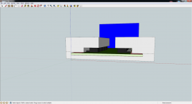
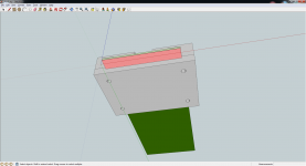
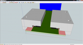
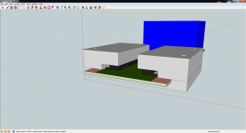
In the meantime, I drew up a possible suggestion for a chassis mount heatsink that would be very effective at removing heat, but does look a little plain (sorry qusp!)
I would propose a base plate with two clamshell style clamps that bolt down from the top. This assembly could be bolted onto the board using a single thin piece of insulator across the bottom and folded up around the side onto the top. It would be very reasy to machine, and would be effective at pulling heat off both the PCB and the top of the parts.
The bottom plate could be made any standard thickness, and normal standoffs could be used to support the rear. The bottom plate could be threaded and allow it to be bolted to the bottom of any flat aluminum chassis.
This could allow a variety of different extruded chassis to be used including something like this:
Box Enclosures - New Page
You would simply need to drill six clearance holes in the bottom, toss the amp in, and screw it in place from the outside bottom.
As for connectors, I have a strong preference for the Neutrik connectors for the following reasons:
1. Single cutout for BAL or SE operation
2. Very good quality connectors
3. Very well priced connectors
4. Easily available anywhere in the world
I have a particular disdain for non-standard connectors as they always come back to bite you in the end. Someday, somehow, you'll be at someone's house wanting to demo your great new amp, but the custom lemo to XLR cable you made won't be long enough and you'll be out of luck. I've been there, and it's really crummy.
I would personally opt for the following rear panel layout:
XLR/RCA Neutrik (one or the other, not both) - output binding posts - IEC (with or without a switch and a fuse).
Any thoughts or comments are welcome!
Cheers,
Owen
I sent off the DXF file for the PCB to Hypertune, and hopefully he can use that to get a more accurate cad model of the board and parts.
In the meantime, I drew up a possible suggestion for a chassis mount heatsink that would be very effective at removing heat, but does look a little plain (sorry qusp!)
I would propose a base plate with two clamshell style clamps that bolt down from the top. This assembly could be bolted onto the board using a single thin piece of insulator across the bottom and folded up around the side onto the top. It would be very reasy to machine, and would be effective at pulling heat off both the PCB and the top of the parts.
The bottom plate could be made any standard thickness, and normal standoffs could be used to support the rear. The bottom plate could be threaded and allow it to be bolted to the bottom of any flat aluminum chassis.
This could allow a variety of different extruded chassis to be used including something like this:
Box Enclosures - New Page
You would simply need to drill six clearance holes in the bottom, toss the amp in, and screw it in place from the outside bottom.
As for connectors, I have a strong preference for the Neutrik connectors for the following reasons:
1. Single cutout for BAL or SE operation
2. Very good quality connectors
3. Very well priced connectors
4. Easily available anywhere in the world
I have a particular disdain for non-standard connectors as they always come back to bite you in the end. Someday, somehow, you'll be at someone's house wanting to demo your great new amp, but the custom lemo to XLR cable you made won't be long enough and you'll be out of luck. I've been there, and it's really crummy.
I would personally opt for the following rear panel layout:
XLR/RCA Neutrik (one or the other, not both) - output binding posts - IEC (with or without a switch and a fuse).
Any thoughts or comments are welcome!
Cheers,
Owen
Attachments
well i suppose i could just use the placement for the neutrik xlr/rca for a speakon output and punch an extra hole for lemo input on mine. and for those that like bling, the cardas XLR is the same D size and fits perfectly. but please make it rear mount, the surround on the neutriks is rough/dodgy imo and having a big square mounted externally looks bad. rear mounted they look quite good, the build quality is pretty decent/rugged, but that surround is made to a budget and i think they assume that anyone that mounts it externally doesnt care about appearances as its in a pro sound environment
dont really care that much about interfacing with other peoples gear and besides you could simply plug any old XLR cable into it to extend it. i cant think of anywhere i would be demoing that wouldnt have an XLR cable.
having a smaller enclosure that looks neat and tidy when i'm going to the trouble of a custom enclosure, that makes me smile 12 months of the year vs the small possibility of being somewhere I want to demo 1 day a year that doesnt have an XLR cable; is a risk i'm willing to take.
maybe not everyone is, thats all good; i said when i mentioned it it probably wouldnt be for everyone
@ hochopeper, not necessarily, i'm starting to worry a little. i have to make this fit with my system with the rest of my builds that are already underway and that includes interface connectors.
I guess i'll just wait and see what HYPERTUNE comes up with
its not easy being green
Last edited:
haha the phantom lives! [@qusp I was wondering if he was some sort of alter-ego of yours
We were conjoined and separated at birth
We were conjoined and separated at birth
indeed and i hate it when he eats that fermented Japanese crap, leaves a bad taste in my mouth and i wake with an insatiable thirst for sake.
@ hochopeper, not necessarily, i'm starting to worry a little. i have to make this fit with my system with the rest of my builds that are already underway and that includes interface connectors.
I guess i'll just wait and see what HYPERTUNE comes up with
its not easy being green..er... i mean blue
it will of course help if its blue =)
Owen:
What about cooling the regs? My idea was to create a sealed unit with no or minimal ventilation. Other than that, it looks good to me and would be easy to make.
I don't know about you, but I've been thinking of what you could come up with if custom heatsinks were a consideration from the beginning. I'm picturing the regs and buffers on the bottom of the board. Regs would be mounted flat, with holes through the pcb for mounting screws, and the heatsink would essentially just be a flat bar with holes for mounting to a chassis.
i'm not Owen, but the NTD1 has illustrated that you dont have to have mounting holes through everything, i'm pretty sure you could mount the regs on the bottom, invert them so the pinout matches and bend over so they contact the sink; they wont put out a heap of heat.
you would still have the height of massive caps, so i dont know how much space could have been saved? and its all academic now right? but yeah i dont see a problem with mounting the regs on the bottom, but you might then want to turn the entire unit over either on its side or upside-down so the dissipation is better, the orientation of the parts inside doesnt matter, the only thing that might perhaps is the caps, but i doubt that too
i love the idea of the basically sealed unit (with wire channels?) i think owen is trying to save you some time, but i reckon youve probably already done a lot of the work? (or at least conceptualised it) you are the only one that can tell us what time you have for the project and what is possible without too much work. as long as the original heatsink mounting holes are still there there is an option for those who dont want the case, so i reckon satisfy yourself mate, pretty sure you could come up with something better than we can conceive as we dont know the limits of the tools like you do. that includes ignoring me, i'll still buy it unless its gold or some **** lol
i know as a graphic designer i always did/do better work when the customer trusted in me enough to just let me go at it and do what i did best and from what ive seen of your work and workshop, you are well deserving of that trust
Last edited:
- Home
- Amplifiers
- Solid State
- The Wire - Low Power Ultra High Perfromance (LPUHP) 16W Power Amplifier