could it be designed so that you could do either via an interlocking system? just a thought. i would probably go for monoblocks i guess; as it is its breaking the system i had planned for my other amps, which is to have a central power supply with control circuitry for the 2 'mono' units, so a 3 box build for dual mono, but given the onboard power supply of the LPUHP this isnt really possible. i do like the idea of a stereo unit as it would simplify input connection to a single 4 pin, but mono makes it easier to place the units closer to the speaker
so i guess overall mono would be preferred.
Just a thought, and kind of unrelated to the chassis design, it would be pretty easy to ignore the onboard power supply on the pcb if you wanted. It is after all just a simple lm317/lm337 supply. You could easily recreate this in another chassis, or use some other power supply, and then tie into the rails in the amp part of the pcb.
Last edited:
of course, but i would only do that if i'd chopped it off rather than having all that wasted space. one could also relocate just the transformer and bridge to another case and leave up to the bridge unpopulated, feeding the onboard reg DC. i think it would be very unwise to have the regulator in another case, sure there is a fair bit of local decoupling, but its not something I would consider for a project of this calibre
oh i see i forgot to mention it on this page...
no, there are no PCBs or kits left
oh i see i forgot to mention it on this page...
no, there are no PCBs or kits left
Hi Guys,
I shipped out a big batch of these this evening, and the updated list is posted below.
Everyone highlighted in yellow has been shipped this evening.
I'm still waiting for three payments:
bada bing
sharpi31
Wolfsin
All packages shipped out via letter mail since it's cheap and there are no customs forms to fill out. There is no tracking on these as registered mail is very expensive.
Cheers,
Owen
Attachments
Last edited:
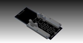
Here is a quick model of a part that would enable the chassis to work as the heatsink.
Could be made to cover the top of the buffers as well.
Would be attached to the PCB from underneath using the buffer heatsink screw holes. Not sure what would be required with regard to electrical insulation.
It could be simplified if the variable resistors were placed underneath the board, but it's no problem either way.
Attachments
Looking good mate!! I see no problem with the pots installed on te bottom personally, as it should pretty much be set before you stuff the amp section anyway using a dummy load and then since you could safely run without heatsinks for setup, then just stuff the remainder of the board. we could build, set then install in the chassis when all is confirmed kosher.
Last edited:
Looking good mate!!
Looks great!!
Pots per standard bom are 9.8mm high + 1.3mm for adjusting screw so we won't be using 10mm spacer if mounting them underneath. Alternatively there is a T93XA variant of the same pot that has a side mounted adjustment screw. That is 9.8mm high so would still be a pretty damn tight fit with a 10mm spacer.
Simplest option might be to move board to 15mm above floor of enclosure.
I might be a little slow; could you help me understand where the contact is between those aluminum pieces and the chassis?Here is a quick model of a part that would enable the chassis to work as the heatsink.
Could be made to cover the top of the buffers as well.
Would be attached to the PCB from underneath using the buffer heatsink screw holes. Not sure what would be required with regard to electrical insulation.
It could be simplified if the variable resistors were placed underneath the board, but it's no problem either way.
Thanks guys.
If Owen gives the OK, I'll continue with a chassis design to suit.
qusp: do you know of any rca and balanced sockets that share a common mounting flange? Would be good if I could machine the chassis in a way that would allow individuals to chose either socket.
Edit:
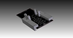
454Casull: the chassis would be machined in a way that would allow the aluminium bars to bolt on using the 3 holes either side of the board.
I could extend the bars downwards further so they could be bolted to any chassis though. Attached pic to show what I mean:
If Owen gives the OK, I'll continue with a chassis design to suit.
qusp: do you know of any rca and balanced sockets that share a common mounting flange? Would be good if I could machine the chassis in a way that would allow individuals to chose either socket.
Edit:
454Casull: the chassis would be machined in a way that would allow the aluminium bars to bolt on using the 3 holes either side of the board.
I could extend the bars downwards further so they could be bolted to any chassis though. Attached pic to show what I mean:
Attachments
Last edited:
An externally hosted image should be here but it was not working when we last tested it.
This box is advertised as 9 5/8" x 5" x 4 1/8" and available for $13.50. I would lose the end caps and replace with something more appealing. I would also want to tap and extend the sinks referenced by HYPERTUNE to provide contact with the finned portion of the case.
qusp: do you know of any rca and balanced sockets that share a common mounting flange? Would be good if I could machine the chassis in a way that would allow individuals to chose either socket.
Knowing qusp's preference for lemo and eichman I think a 12mm penetration in the enclosure may get the job done for RCA and balanced having just had a look at their datasheets. Depending on which lemo model he prefers it may be slightly less than that.
qusp really should confirm the above, he's done a lot more work with both of these, I've never set eyes on either.
The eichman binding posts specify an 8.5mm hole in enclosure.
You run into the same problem that you did elsewhere; if the distance between the chassis and the top of the board isn't exactly how you design it (tolerance-wise, too), you'll either end up with a loose clamp or a gap between the aluminum bridges and the chassis. If you design something so that the clamp is separate from the heat bridge, it should be much easier to guarantee tight contact on both interfaces.Thanks guys.
If Owen gives the OK, I'll continue with a chassis design to suit.
qusp: do you know of any rca and balanced sockets that share a common mounting flange? Would be good if I could machine the chassis in a way that would allow individuals to chose either socket.
Edit:
454Casull: the chassis would be machined in a way that would allow the aluminium bars to bolt on using the 3 holes either side of the board.
I could extend the bars downwards further so they could be bolted to any chassis though. Attached pic to show what I mean:
Looks great!!
Pots per standard bom are 9.8mm high + 1.3mm for adjusting screw so we won't be using 10mm spacer if mounting them underneath. Alternatively there is a T93XA variant of the same pot that has a side mounted adjustment screw. That is 9.8mm high so would still be a pretty damn tight fit with a 10mm spacer.
Simplest option might be to move board to 15mm above floor of enclosure.
side mounted is no good and a pita to work with imo, i dont think we'll be relying on spacers to do the spacing somehow anyway
Knowing qusp's preference for lemo and eichman I think a 12mm penetration in the enclosure may get the job done for RCA and balanced having just had a look at their datasheets. Depending on which lemo model he prefers it may be slightly less than that.
qusp really should confirm the above, he's done a lot more work with both of these, I've never set eyes on either.
The eichman binding posts specify an 8.5mm hole in enclosure.
indeed i do prefer lemo, but i doubt others will be up for having to make an XLR to lemo cable. they only need 9.1mm actually and bugger all rear space, if others are keen i'm sure we could get the costs down between us, cheaper than your entry level audiophile type XLRs and would free up quite a bit of space as well as improving CMMR (true, but mainly a joke). but yeah the ETI cablepods and speakon are definitely my preference and i know Hypertune is using the ETI on the bigger brother wire poweramps.
hell if people were interested i could look at doing a custom set of interconnects for the group at a nice price. not too bling, just high quality
but in answer to Mark's question, i do indeed know a standard one that can be used for either, though I wont be using them i dont think as lemo only needs a small round hole i could probably arrange to work that out somehow.
the neutrik D mount series RCA and XLR
An externally hosted image should be here but it was not working when we last tested it.
An externally hosted image should be here but it was not working when we last tested it.
me, i'd be going for the lemo EGG.0B.302.CLL

Last edited:
The eichman binding posts specify an 8.5mm hole in enclosure.
That's for the post itself but there is a clearance of 12.7mm (for memory) required for the mounting plate to sit flush with the panel/case/speaker.
 its ok, HYPERTUNE is using them on his other amps, he'll have the part already modelled up
haha the phantom lives! [@qusp I was wondering if he was some sort of alter-ego of yours  ]
]
Those neutrik sockets will look comically large @31mm wide compared to a pcb that is only 65mm wide! The enclosure width/height will be dictated by size of connectors on the back panel rather than size of gear we've got inside it. Just a standard IEC socket and a single rca/xlr socket takes up the entire rear profile of the amp. Which makes it hard to minimize amount of materials used. Obviously hypertune is all over that issue but just worth pointing out.
]Those neutrik sockets will look comically large @31mm wide compared to a pcb that is only 65mm wide! The enclosure width/height will be dictated by size of connectors on the back panel rather than size of gear we've got inside it. Just a standard IEC socket and a single rca/xlr socket takes up the entire rear profile of the amp. Which makes it hard to minimize amount of materials used. Obviously hypertune is all over that issue but just worth pointing out.
Surely you're going to give an amp of this assumed quality a captive lead and not damage the sound quality with an awful IEC mains connector? I spent months testing and comparing a load of them and even the Wattgates, with every kind of plating and soldered, etc, are awful compared to captive.
Brass RCA plugs and sockets are awful too. And so are those cheaper PCB mounted RCA pair / quad rear sockets (jacks?) that are so popular. I know this because we have them on our integrated amplifier (the commercial product that I co-developed and sold 10 years ago). Recently for a customer I drilled two holes in the chassis under the sockets and took the wires through and in and soldered them direct. Very much better, surprisingly so as he already had Eichmann copper plugs on there and those plugs 'killed' the 'high' and low quality brass ones that he and I and a lot of Hi-Fi people I know are now deleting from our systems.
So captive interconnects are the way to go as well
And captive means a smaller end plate and case size
Last edited:
- Home
- Amplifiers
- Solid State
- The Wire - Low Power Ultra High Perfromance (LPUHP) 16W Power Amplifier