Build with trimmer was what I had in mind after I posted my own original attrocious bias calculation back here ...
It doesn't answer the question about if the switching relay circuit has any tangible impact on the compensation circuit ...
yep, any prediction will only be an approximation, as all fets will be different and then different again vs temp and vs supply voltage. so build and measure is it.
yeah the relay thing, I emailed Owen last night preemptively and hopefully he can give some idea. I reworked a second optional layout that only places the 2 individual relay + resistor sub-circuits in parallel, without putting the 2 relays and their parasitic elements in series. whether thats meaningful depends on whether 1 has a meaningful effect.
its an interesting issue that, bias current vs VGS bias voltage prediction, ive never had to do it before. i've only ever used a trimmer and then occasionally replaced that trimmer with a fixed resistor after measuring the resistance and now I know why, so i've never really looked into all the factors that come into play before now.
even armed with the datasheet curves its a crapshoot and extensive googling has turned up nothing, just others mentioning the factors at play ie VGS vs ID, transfer admittance, rdsON and tempco, probably Ciss too, but everyone just ends up saying build and measure. I guess modelling will give some approximation if you have good models, but the specific operating conditions and individual devices will still impose themselves on the results.
anyone else got any more general rules of thumb? I guess i'll just continue in the same manner I always have.
Last edited:
yep, any prediction will only be an approximation, as all fets will be different and then different again vs temp and vs supply voltage. so build and measure is it.
yeah the relay thing, I emailed Owen last night preemptively and hopefully he can give some idea. I reworked a second optional layout that only places the 2 individual relay + resistor sub-circuits in parallel, without putting the 2 relays and their parasitic elements in series. whether thats meaningful depends on whether 1 has a meaningful effect.
I might be stating the bleeding obvious, but my vote is that series vs parallel for parasitic elements comes down to whether the parasitic capacitance or inductance is the larger issue. If capacitance is to be minimised, have them in series.
depends on what you call consistent, they are quite consistent for random unmatched devices, using a fairly simplified 2 point technique that doesnt really represent the operating conditions in this amp the way we ourselves will use them, but they dont really qualify as matched and they probably exhibit more differences under dynamic conditions.
yes you are stating the obvious") thats why I mentioned to you it was an optional layout, not an improved layout, which is best remains to be seen and hinges on which of these effects is more important. 2 x series fet relays vs 2 x parallel fet relays bandwidth and the impact of that is another.
thats why I mentioned to you it was an optional layout, not an improved layout, which is best remains to be seen and hinges on which of these effects is more important. 2 x series fet relays vs 2 x parallel fet relays bandwidth and the impact of that is another.
yes you are stating the obvious
thats why I mentioned to you it was an optional layout, not an improved layout, which is best remains to be seen and hinges on which of these effects is more important. 2 x series fet relays vs 2 x parallel fet relays bandwidth and the impact of that is another.Hi Guys,
My understanding of the bias circuit is that it is indeed a 2mA CCS, and the BW of your fet based relay should not have any impact.
The same bias setup also supports a VBE multiplier (covered in detail in the App Note) and again, the transistor used has no influence on the operational performance of the amp, only the bias level. I have independently verified that.
I'd say you guys are safe, but it's always a good idea to test before making boards, so I'll leave that out there
Capacitance across the lower bias resistor is not an issue at all, so parallel operation (shorting the existing resistor with lower values) is probably preferable. Definitely do not touch the upper bias resistor, or the terminal it's connected to! It's an extremely sensitive node.
Series operation in the main bias loop is strongly discouraged as failure of the fet element in the relay could spell disaster.
As for matching and variances, I really wouldn't worry about it. You could individually trim each amplifier to get them perfectly matched, but I don't think that would be worth the effort. An amp biased at 360mA isn't going to sound or measure any differently than one biased at 365mA or 370mA.
Cheers!
Owen
Robert F
If you read back a couple of pages someone was not able to finish their kits so give them a shout.
Post 2074
Thanks for that, I was too late but it seems someone else may be able to help.
Hi Guys,
My understanding of the bias circuit is that it is indeed a 2mA CCS, and the BW of your fet based relay should not have any impact.
The same bias setup also supports a VBE multiplier (covered in detail in the App Note) and again, the transistor used has no influence on the operational performance of the amp, only the bias level. I have independently verified that.
I'd say you guys are safe, but it's always a good idea to test before making boards, so I'll leave that out there
Capacitance across the lower bias resistor is not an issue at all, so parallel operation (shorting the existing resistor with lower values) is probably preferable. Definitely do not touch the upper bias resistor, or the terminal it's connected to! It's an extremely sensitive node.
Series operation in the main bias loop is strongly discouraged as failure of the fet element in the relay could spell disaster.
As for matching and variances, I really wouldn't worry about it. You could individually trim each amplifier to get them perfectly matched, but I don't think that would be worth the effort. An amp biased at 360mA isn't going to sound or measure any differently than one biased at 365mA or 370mA.
Cheers!
Owen
Thanks Owen!
The price of the boards is so small (2L 10mmx15mm PCB) that I'd be happy to make both, though we're both short of equipment to test for any differences. If one is a Bad IdeaTM then it would save me the eternal self doubt of wondering if I've hamstrung your amp design unnecessarily.
Regarding reliability, obviously it depends if the relay fails open or fails to a short circuit.
Here is the reliability test data from the manufacturer for this series of Form B (NC) relays - http://www.ixysic.com/Index/QualityReports/CodeA1.pdf
They also have this 'app note' - http://www.ixysic.com/home/pdfs.nsf/www/AN-145.pdf/$file/AN-145.pdf - though I feel that the app note is more of a sales brochure to push SSR over EMR.
Their discussion on failure modes is disappointingly light on details on whether we should expect to have a NC relay fail to an open state, which would be critical information I'd be looking for if I was designing an intrinsically safe system so I expected to find that info.
After reading that though I get the impression that the SSR, if tested before put into use, is a very reliable device, so I'm not going to stress too much about failures.
Chris
thanks for that Owen, yeah I read the vbe version, which is as you say covered in more detail, but didnt connect the dots that they hadnt mentioned the choice of transistor as a factor, so bandwidth must ot be a concern. these PCBs will be very cheap, i'll send you a couple to try. its not worth worrying about the cost of a second PCB, just the wasted time/effort in going a direction we should be.
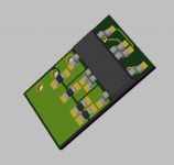
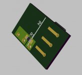
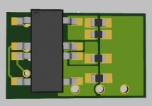
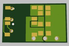
OK parallel it is. heres the 2 layouts. option 1 was the version that places the relay in series with the first relay (in order to put the resistances in parallel ) looks neater/cleaner, but looks can be deceiving. the 'IN' point is just showing the direction to solder the control voltage connection, not indicating the CCS input
its 14mm x 8.75mm
OK parallel it is. heres the 2 layouts. option 1 was the version that places the relay in series with the first relay (in order to put the resistances in parallel
) looks neater/cleaner, but looks can be deceiving. the 'IN' point is just showing the direction to solder the control voltage connection, not indicating the CCS inputits 14mm x 8.75mm
Attachments
-
 iso-remote triggered bias F option1.png34.6 KB · Views: 469
 -
 iso-remote triggered bias rear option1.jpg40.8 KB · Views: 464
 -
 iso-remote triggered bias fr option2.jpg54.7 KB · Views: 469
 -
 iso-remote triggered bias rear option2.jpg52.1 KB · Views: 444
 -
 iso-remote bias rear option2 blank.jpg48.1 KB · Views: 442
Just to make sure my I've got my thinking straight for creating a Low/Mid/High bias circuit:
Guestimate; low [50mA] = 90 Ohm / Mid [360mA] = 790 Ohm / High [600mA] = 1500 Ohm
R1 = 1.5K Ohm
R2 = 1.65K Ohm
R3 = 102 Ohm
Low: R1, R2, R3 in parallel = 90.3 Ohm
Mid: R1, R2 in parallel = 786 Ohm
High: R1 = 1.5K Ohm
That correct?
Guestimate; low [50mA] = 90 Ohm / Mid [360mA] = 790 Ohm / High [600mA] = 1500 Ohm
R1 = 1.5K Ohm
R2 = 1.65K Ohm
R3 = 102 Ohm
Low: R1, R2, R3 in parallel = 90.3 Ohm
Mid: R1, R2 in parallel = 786 Ohm
High: R1 = 1.5K Ohm
That correct?
Last edited:
are you pushing ahead to do the same thing in parallel with us somehow? we'll be doing PCBs in the next week based on the design I posted on the previous page. they have optically isolated relays to switch the resistors into circuit. there is a 3 wire connection to the adapter with ground and 2 control voltages that will connect to an arduino like circuit with wifi connection, an actual arduino or even a plain electrical/mechanical switch will work to switch the relays too. but the switching voltage and ground is optically isolated from the amp.
regarding your numbers, I dont know, is it correct? you have an amp (at least one) running, as weve just discussed, build and measure is really the only way to get accuracy, given the variance of each individual fet and the operating conditions will impact on the amount of resistance needed to create the correct bias voltage and by extension current.
your parallel resistance calculations are approximately correct though.
It would be daft to run in parallel, just wanting to get the way it works right in my head. As the control method is fairly adaptable it would be worth getting a pair from you once they're fabricated.
I would at least want a low start up bias, then switch to a higher running bias. Either 360mA or =>600 mA.
Just double checking the reading again for 360mA, it's 690 Ohm, the other two were rough guesses at values. I will set the bias first then measure to obtain the correct R values.
With the Above I just wanted to make sure that I needed two/three resistors in parallel to get the low setting, then switch out the second/third resistor to get the higher bias. Was easier putting numbers in rather than A,B,C...
I would at least want a low start up bias, then switch to a higher running bias. Either 360mA or =>600 mA.
Just double checking the reading again for 360mA, it's 690 Ohm, the other two were rough guesses at values. I will set the bias first then measure to obtain the correct R values.
With the Above I just wanted to make sure that I needed two/three resistors in parallel to get the low setting, then switch out the second/third resistor
no probs, didnt mean to sound terse, i'm not annoyed at all was just a bit baffled.
the settings will be completely up to you, people can set it how they like. yes the idea is to start up into ~110ma (below 100-110ma the ALFETs are not neutral tempco, so I would not recommend 90ma) then select one of 2 other settings depending on temperature or your heatsinking, or just preference for higher class A bias. actually they are speaking of the ALF08N20V rather than ALF16N20V in that app note, but it probably holds true to some degree.
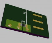
the highest bias setting is just a single resistor, with no relay, right next to the pins directly across them. Actually I have put 2 parallel resistors for the high bias position to allow more accurate tweaking and 2 parallel for the lowest, to again make it easier to achieve a low bias. the middle bias setting (one relay open) only has one position, as I feel this is probably less critical. we may end up going with a thin film resistor network instead of discrete resistors, if that can be made to work.
so R1A, R1B (front and back directly accross the pins) is high bias, R2 with the relay open places that in parallel to create the mid setting, then the second relay opens to place R3 in parallel and create the low/start up bias.
I may, or may not put some resistors and maybe even an external LED on there to both make sure the internal LED in the relay is biased ON, as well as indicate which setting is in use. from the datasheet 1ma approx is needed to assure switching, so will depend on what you are driving it with, whether something is needed.
the settings will be completely up to you, people can set it how they like. yes the idea is to start up into ~110ma (below 100-110ma the ALFETs are not neutral tempco, so I would not recommend 90ma) then select one of 2 other settings depending on temperature or your heatsinking, or just preference for higher class A bias. actually they are speaking of the ALF08N20V rather than ALF16N20V in that app note, but it probably holds true to some degree.
the highest bias setting is just a single resistor, with no relay, right next to the pins directly across them. Actually I have put 2 parallel resistors for the high bias position to allow more accurate tweaking and 2 parallel for the lowest, to again make it easier to achieve a low bias. the middle bias setting (one relay open) only has one position, as I feel this is probably less critical. we may end up going with a thin film resistor network instead of discrete resistors, if that can be made to work.
so R1A, R1B (front and back directly accross the pins) is high bias, R2 with the relay open places that in parallel to create the mid setting, then the second relay opens to place R3 in parallel and create the low/start up bias.
I may, or may not put some resistors and maybe even an external LED on there to both make sure the internal LED in the relay is biased ON, as well as indicate which setting is in use. from the datasheet 1ma approx is needed to assure switching, so will depend on what you are driving it with, whether something is needed.
Last edited:
A few things to note.
This adjustable bias function is of interest to all users of these LME49830 The Wire amplifiers, not just those using the SMPS, though they're more interesting to those with the DPS600 - because it won't start under the load of a high bias setting. If you're chasing the last few % of performance, switching bias setting based on a measured ambient temp will certainly keep your amp within it's safe operating area more readily.
I was going to put an indication LED on the controller that I design (pcb layout for that starting in the next few days). I personally think it is better to have the LED on the controller rather than on this PCB, even though it will be on the isolated side of the board. The controller will have resistors and LEDs to set the current for optimal operation of the relay. The fewest possible devices on this board seems the best approach. The controller will allow input of 3 or so temperature sensors ambient + two heatsink temperatures for independent thermal protection of each amp - will have a shutdown threshold as well as thresholds for switching between bias levels.
yes but not everyone will be using the controller will they? and the indication stuff (just 2 parts each position) can just be left out if you dont want them, I like the idea of the LED indication on the device itself, it shows at a glance that its operating as expected and it doesnt take up any extra space and certainly doesnt have any negative consequence. ive become attached to LED indication from Ians designs, it makes troubleshooting easier as you can see straight away if an LED is on, glowing too brightly, flickering etc.
doesnt mean you need delete the ones on the controller
doesnt mean you need delete the ones on the controller
Last edited:
- Home
- Amplifiers
- Solid State
- "The Wire AMP" Class A/AB Power Amplifier based on the LME49830 with Lateral Mosfets