I can not find a schematic or service manual for Knoll MA205.
30VAC sounds correct for a 50W/ch amp.
So if it is a center tapped transformer, then you will have 15VAC to the center tap.
make a full wave rectifier using two diodes(1/2 of a bridge) and the center tap is ground.
question is what else is that supply used for? if other circuits really on the supplies the way they are configured you will have to stay with the split supply and use a regulator to drop down the voltage to <28V
Screwing around with a old receiver/amp, you really need to know a bit about electronics.
Noop, it is the peak you are concerned about, not the average, electronics 101.Half-wave rectification might be the way to go. You essentially lose half your power, but at least it gets you into the right voltage region for the Wiener.
Last edited:
Alright, got the pics into flickr
https://www.flickr.com/photos/54684593@N08/with/17052085179/
I want to power 2 Wieners for biamping. One to drive woofers that are 4ohms, and the other for tweeters that are 8 ohms. I have a multimeter that tells me volts, amps, and ohms readings. If you think I should stop screwing with it and go with a SMPS instead, I will. Just hard to not use that nice toroidal transformer! My plan is to just keep the transformer and gut everything else inside the amp. Wire the transformer to a new rectifier. Feed the rectifier outputs to 2 Wieners, then add new wires from preamp/RCA inputs and speaker binding post outputs to the Wieners. If some step-down should go between rectifier and the wiener, I think I can do it if you tell me what to buy or what parts are needed to build a custom step-down. Or maybe split the wiring from transformer (3 wires out) to the rectifier/diode+cap. like Rsavas says. I will be careful to unplug the power cord when building and check the final VDC before powering the wieners.
Last edited:
Noop, it is the peak you are concerned about, not the average, electronics 101.
This is the way I understand it:
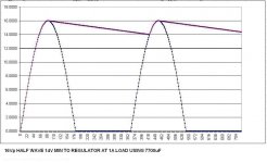
30VAC with full-wave rectification = ~30v * 1.414 = ~42vdc (too much for the Wiener)
30VAC with half-wave rectification = ~15v * 1.414 = ~21vdc (about right for the Wiener)
The 1.414 factors in the peak. Care to explain my error?
My advise, leave the amp alone and do a separate PS for wiener.
Regardless of the rest of the discussion, I agree with this.
i'll let some one else do it for me.Care to explain my error?
Unregulated Power Supply Design
the center tapped transformer example i discussed above is shown in fig 3. look at fig 8 for your 1/2 wave rect example.
Oh well, any recommendation for a SMPS then, or Cogitech can you give me the parts list of what you have for PS?
FWIW, I tried a 24v SMPS first, then the little linear supply I slapped together. I like the linear supply better. The SMPS sounds "leaner" to me, despite the fact that it has more VA.
The (3) components in my linear supply are (as seen in photo):
- A cheap ($6) 12v 40VA transformer that I got off ebay, a long time ago
- A big-***, way overkill, bridge rectifier which I had in a junk box
- A Nippon Chemi-Con 3300uF/50v electrolytic capacitor
There's all kinds of transformers on ebay. You can safely buy anything up to ~16v and it'll still be safe once rectified.
The bridge rectifier only needs to be rated for ~5A. Your transformer will likely not push 5A anyway. I use one rated way too high, because I had it already.
The smoothing cap can be anything from 1000uF to 1 farad. Practically speaking, something around 3300uF to 4700uF will work well and fit in whatever chassis you choose. It is always a good idea to use a cap with some voltage headroom. A 25v cap will be good enough if you are only going to run rectified 12vac (~17vdc). If you find a 16v transformer and your rectified voltage winds up closer to 23-24v, then use a 50v cap.
Even if you had to buy the components, you could put together two of these supplies (one for each Wiener) for very little money. Like $20, total. More if you aren't as good as me at finding poorly-listed items on ebay
")
Before doing all of this, though, keep in mind that many, many people state that 19v laptop bricks (which are also SMPS) sound amazing. I have a number of these supplies from HP, Lenovo, etc. All I can say is that yes, they do power these amps. I just like the linear supply better. I cannot explain why, and you may have the opposite reaction if you listened.
i'll let some one else do it for me.
Unregulated Power Supply Design
the center tapped transformer example i discussed above is shown in fig 3. look at fig 8 for your 1/2 wave rect example.
I've already studied that information. I still do not see my error.
You assumed that I missed the fact that "peak" voltage is what matters, not RMS. I already know that, which is why I use the 1.414 multiplier in my calculations.
If full-wave rectification of 30VAC results in 42VDC output, then half-wave rectification will result in 21VDC. It is that simple, and the calculation is based on peak-to-peak, not RMS.
Measure across the 3 outputs of the transformer - if you're getting 30VAC from orange to yellow and 60VAC from orange to orange, you're SOL. If you're getting 30VAC across the orange windings, and 15VAC from either orange wire to yellow, you're set. 15VAC will rectify to about 21VAC, which is plenty.Alright, got the pics into flickr
https://www.flickr.com/photos/54684593@N08/with/17052085179/
I want to power 2 Wieners for biamping.
Technically you only need two diodes to make a half bridge rectifier, but I'd use a full bridge rectifier package anyway since it bolts to a chassis easily. Orange leads to the ~ terminals, yellow to ground, + output, - disconnected.
retraction,My advise, leave the amp alone and do a separate PS for wiener.
now that i look at the pic of the amp guts and what gmarsh is saying with the org/yel secondary wires.
the item with the winged heatsink is the rectifier, probably a bridge rect.
i am guessing a lm3886 based amp
I've already studied that information. I still do not see my error.
You assumed that I missed the fact that "peak" voltage is what matters, not RMS. I already know that, which is why I use the 1.414 multiplier in my calculations.
If full-wave rectification of 30VAC results in 42VDC output, then half-wave rectification will result in 21VDC. It is that simple, and the calculation is based on peak-to-peak, not RMS.
IMHO your error is in your understanding of "half wave rectification"
But this should be discussed on another thread.
Apologies ,GM
Attachments
Last edited:
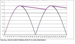
Why using half-wave if the output windings can be just paralleled? If it's a center tap transformer, then go for it. Double current, half ripple due to full wave.
Yes. If it is centre-tapped 30v, then Gary's solution works perfectly.
IMHO your error is in your understanding of "half wave rectification"
But this should be discussed on another thread.
Apologies ,GM
I agree that it is off-topic, and I will study this closer now. I do realize that I misunderstood it. I guess I shouldn't rely too heavily on randomly googled info. Apologies to rsavas for being stubborn.
Yes. If it is centre-tapped 30v, then Gary's solution works perfectly.
Gary's solution isn't paralleled, is half wave as it is using the outer taps. Parallel would be both orange to one side ~, yellow to the other ~.
cool how about stubbornly confused !Apologies to rsavas for being stubborn.
wow more confusion.Gary's solution isn't paralleled, is half wave as it is using the outer taps.
so it would technically be called a "full-wave,half bridge rectifier, using a center tapped transformer"Technically you only need two diodes to make a half bridge rectifier,
That would short the transformer output. Doable if the transformer had two separate 15V windings (just parallel 'em) but with a single center tapped 30V winding, the two orange leads are out of phase.Gary's solution isn't paralleled, is half wave as it is using the outer taps. Parallel would be both orange to one side ~, yellow to the other ~.
- Home
- Group Buys
- "The Wiener" TPA3118 amplifier card