Forane12,
Thank you, but just a warning (not sure if this is OK with you) - when working with the PCB Ill need to solder test points to help diagnose the root cause if the earlier measurements are confirmed...
Not sure you would be happy with your PCB being modified / hacked")
Would gladly sacrifice one if it is OK with Ian and if it is the latest version, I lost track of the GBs and which version I have.
So an OK from is Ian is all I need. Apart from an address to send it to of course
You can use mine john. No issue with attacking it.
Choice of clocks available - if required.
When performing Low frequency, high dynamic range Phase noise measurements - an oscilloscope is not a capable tool (they dont have the dynamic range, reference time-base stability, thermal stability or memory depth), where as the phase noise measurements systems such as the TimePod / E5052 etc. are designed for this very purpose...
Unlike earlier phase noise system, making PN measurements is child's play, and pretty much infallible... Knowing the TimePod, I suspect there's a good chance I'll confirm Andrea results, but whats more important is to understand the cause so I can get this information back to Ian.
John,
I agree with you, but how can the jitter measurement help "to understand the cause"?
It does not help, it's a single numeric value that explain nothing about the spectrum of the noise, so it's useless to understand the issues and to solve them.
I dont agree that you can ignore the spurs, these will impact the audio quality.
I dont believe Gerhard intentions was to say that spurie could be ignored... just that they could a result of an external signal (AC Magnet field, mains hum) not necessarily due to the oscillator circuit itself - they will however impact audio performance.
I know what Gerhard meant, I mean that the spurs coming from the power supply (100 Hz and harmonics as in the phase noise plot) are not related to the clock and moreover they are easy to remove.
So they are only a annoying element in the phase noise measurement that can be neglected when we are analyzing the performance of an oscillator or a clock.
Absolutely not.
The spurs, in an isolated oscillator measurement are just that, an annoyance, not part of the oscillator physics.
But I would like to repeat, in ! Any real world setup, spurs will be hard coded into the stream, by bad PS, groundloop, crosstalk all that jazz.
I have made a series of these tests years ago.
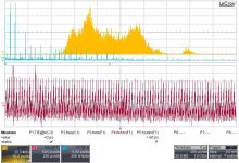
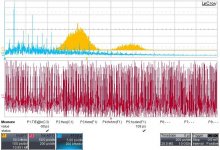
Here it is a bit for having the taste. Also what can be seen on a scope.
Yellow trace is the jitter distribution, like with Ian's test.
Red trace is the waveform of the jitter modulation signal, blue trace is FFT (~phase noise) plot of that trace.
Easily can be indentified the intruder frequencies, there distribution, intensity.
The two plots are my Rotel player SPDIF output, when in idle, and when playing.
The spurs, in an isolated oscillator measurement are just that, an annoyance, not part of the oscillator physics.
But I would like to repeat, in ! Any real world setup, spurs will be hard coded into the stream, by bad PS, groundloop, crosstalk all that jazz.
I have made a series of these tests years ago.
Here it is a bit for having the taste. Also what can be seen on a scope.
Yellow trace is the jitter distribution, like with Ian's test.
Red trace is the waveform of the jitter modulation signal, blue trace is FFT (~phase noise) plot of that trace.
Easily can be indentified the intruder frequencies, there distribution, intensity.
The two plots are my Rotel player SPDIF output, when in idle, and when playing.
Attachments
Last edited:
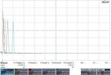
And here is the phase plot when I had been testing an artificially induced fix modulation frequency, sitting on a 10MHz carrier. Modulation frequencies were 100; 200;500; 2000 Hz
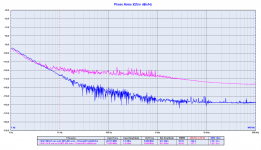
Yes, these are not SOTA results but also absloutely usable down to useful range. Noise pickups and gnd loop problems happen here, not at 1Hz
Yes, these are not SOTA results but also absloutely usable down to useful range. Noise pickups and gnd loop problems happen here, not at 1Hz
Attachments
Absolutely not.
The spurs, in an isolated oscillator measurement are just that, an annoyance, not part of the oscillator physics.
But I would like to repeat, in ! Any real world setup, spurs will be hard coded into the stream, by bad PS, groundloop, crosstalk all that jazz.
I have made a series of these tests years ago.
Here it is a bit for having the taste. Also what can be seen on a scope.
Yellow trace is the jitter distribution, like with Ian's test.
Red trace is the waveform of the jitter modulation signal, blue trace is FFT (~phase noise) plot of that trace.
Easily can be indentified the intruder frequencies, there distribution, intensity.
The two plots are my Rotel player SPDIF output, when in idle, and when playing.
Again, one could easily remove the spurs from the power supply, it's not so difficult to avoid bad PS, ground loop and crosstalk, take a look at the Driscoll's phase noise, there are no spurs. So they only are an annoyance in the plot, again I suggest Rubiola.org.
BTW, FifoPi operates in a different domain, it's clocked from the master clock not from the RPi, so it's enough obvious that the spurs from the source disappear, except for a bad isolation (but without a schematic and a PCB layout it's hard to say).
John,
I agree with you, but how can the jitter measurement help "to understand the cause"?
It does not help, it's a single numeric value that explain nothing about the spectrum of the noise, so it's useless to understand the issues and to solve them.
Just to clarify - I dont advocate a single Jitter measurement number / result (such as saying 1.5pS total Jitter) - this says NOTHING about the all important distribution / spectrum. This is much the case with distortion numbers - who cares if its 0.01% second or harmonic - but 0.01% 7th harmonic, I'm going to have issues with!
For sure Phase noise plots are all important when talking"Jitter" just as distortion spectrum FFT's are - rather then just saying 0.01% THD...
Last edited:
I know what Gerhard meant, I mean that the spurs coming from the power supply (100 Hz and harmonics as in the phase noise plot) are not related to the clock and moreover they are easy to remove.
So they are only a annoying element in the phase noise measurement that can be neglected when we are analyzing the performance of an oscillator or a clock.
For future measurements I think its important to leave the Spurie visible (dont select "remove Spurie" mode).
I noticed on your PCB's that you have use physically large inductors in selected locations, my experience of these is that they are sensitive to pickup external magnetic H fields... these induced "hum" components will be in a critical area of the audio spectrum.
Its possible that its not the case on your PCB, but I'd be pleasantly surprised and a great result if no visible hum at such super low NF levels
Two things yet then I stop trolling.
I will look up an Rpi or convince my Allo usbridge to put out I2S, and will have a look at the raw signals the same way as above.
That could help to show what is happening in those signals, not only in the TimePod frequency range but also above. (i suspect that is the source of discrepancies here)
Lastly I am keeping to what I am saying: also I am in the process of assembling an Andrew Holme phase noise setup, thanks to Gerhard's indication.
Ciao, George
For future measurements I think its important to leave the Spurie visible (dont select "remove Spurie" mode).
I noticed on your PCB's that you have use physically large inductors in selected locations, my experience of these is that they are sensitive to pickup external magnetic H fields... these induced "hum" components will be in a critical area of the audio spectrum.
Its possible that its not the case on your PCB, but I'd be pleasantly surprised and a great result if no visible hum at such super low NF levels
Just shield the Driscoll oscillator with an aluminum box and there are no hum and spurs.
PCB layout is the result of several iterations, just to avoid any interference.
BTW, FifoPi operates in a different domain, it's clocked from the master clock not from the RPi, so it's enough obvious that the spurs from the source disappear, except for a bad isolation (but without a schematic and a PCB layout it's hard to say).
Yes. With respect to the raw Rpi spectra, the Fifopi had cleaned up what? 70? dB spurs at least.. That is much more coherent with Ian's scope shots.
If You would have.started like that, weeks ago, leaving the spurs on (and to be cleaned up by Fifopi) - then nobody, but me for sure would not had started to complain when You point out the problems that remain.
And if spur removal would be that easy, then why nobody can produce a clean jitter spectra, like in the ASR test? And those are not even pushing hard to show the fine details.. (that is doing those tests much more seriously)
Last edited:
Andrea,
When we will be cooled and not arguing..
You yourself will recognize that the correct, engineer's answer is: "both"
Well, let me drive along the way of "both".
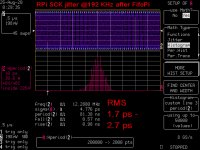
I would assume that you can trust the Timepod SCK measurement since the calculated jitter is almost the same of the one calculated by the digital oscilloscope you trust, 2.7 vs 2.8 ps (picture 1 & 2).
The third picture is the same plot of the first one but using the Driscoll oscillator as the master clock.
Now a few considerations:
- the calculated jitter is almost identical to the one of the master clock (Crystek)
- although someone with high speed logic design experience disagree ("If you have high speed logic design experience, you should know that there is no ideal clock divider in the real world. All clock dividers have additive jitter. A good clock divider normally have a couple of ps of additional jitter. So, 6dB doesn't exist in the real world.") dividing the master clock you should get 6 dB better phase noise. Sometimes the real world confirms the theoretical laws, from 1 Hz to 10 Hz from the carrier the phase noise of the SCK (the master clock divided by 2) is effectively 6 dB better
- above 30 Hz from the carrier the phase noise of the SCK grows, 12 to 30 dB worse than the master clock
- moving to the Driscoll oscillator the calculated jitter decrease to 1.2 ps, but the master clock calculated jitter is 150 fs, one order of magnitude better
- we have lost the 6 dB improvement of the close in phase noise, at 10 Hz from the carrier the phase noise of the FifoPi is 9 dB worse
- above 10 Hz from the carrier the phase noise of the SCK grows, 10 to 30 dB worse than the master clock
Now a few simple questions I hope you would kindly reply:
- the calculated jitter is identical, can you trust the measurement?
- what does 3 ps jitter explains?
- is 3 ps of jitter the "ultimate" performance to be reached?
- why the close in phase noise improvement due to the division disappears with a low noise oscillator?
- why the phase noise grows above 10 Hz from the carrier?
Maybe the answers are the key to improve the performance of the device.
Attachments

andrea_mori's PRi SCK phase noise plot still not correct
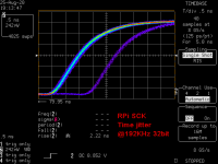
Seems you can make up the phase noise plot by enabling and disabling different suppression. Are you playing with the testing result?
I attached your two times posting RPi SCK phase noise plots. Such a big difference. However, I still can not see the spurs of deterministic jitter at the 1.3 ns in your second plot. (Please find the third picture the analog view of the RPi SCK time jitter to reference). Only 100Hz and orders spurs from the RPi power supply. Your testing result can not be convinced.
The possible problems could be:
1. The integration bandwidth was not enough. To see a bigger picture, normally it needs to be up to the half the carrier frequency.
2. With spurs included, the calculation of RMS phase jitter from the phase noise plot will be different. All spurs have to be integrated. The calculated RMS phase jitter number should much bigger than you did before.
Regards,Ian
It looks like you have not understood, the Timepod integrates spurs when calculating the RMS jitter, so nothing is lost.
Simply the spurs are useless to understand jitter and phase noise, Gerhard has well explained the reasons.
Anyway, since you are so interested on the spurs I turn off the suppression and I attach the plot with spurs.
Now you see the power supply noise (100 Hz) and its harmonics, that are totally useless.
Seems you can make up the phase noise plot by enabling and disabling different suppression. Are you playing with the testing result?
I attached your two times posting RPi SCK phase noise plots. Such a big difference. However, I still can not see the spurs of deterministic jitter at the 1.3 ns in your second plot. (Please find the third picture the analog view of the RPi SCK time jitter to reference). Only 100Hz and orders spurs from the RPi power supply. Your testing result can not be convinced.
The possible problems could be:
1. The integration bandwidth was not enough. To see a bigger picture, normally it needs to be up to the half the carrier frequency.
2. With spurs included, the calculation of RMS phase jitter from the phase noise plot will be different. All spurs have to be integrated. The calculated RMS phase jitter number should much bigger than you did before.
Regards,Ian
Attachments
Last edited:
About spurs and integration bandwidth I suggest a full immersion in the literature you can find at Rubiola.org.
So you will understand the meaning of the power supply spurs and mostly what you have to care about the phase noise at 6 MHz from the carrier (half the carrier frequency).
Moreover you can play with a phase noise to jitter converter to understand that the major contribution to the jitter calculation comes from the close in phase noise and not at 6 MHz from the carrier (that weights nothing).
But as I have already pointed out, if your goal is to remove the spurs from the power supply of the Rpi then you have reached the target.
We have all understood that your real time digital oscilloscope is the reference gear to measure the jitter, so keep out for a while the RPi measurement and focus to the FifoPi SCK and master clock (Crystek) measurements.
Your FifoPi operates in a different domain then we have to assume that it was not source dependent, so the source is not relevant in the investigation.
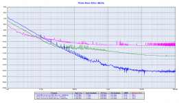
I attach again the phase noise plot of the FIfoPi SCK vs the master clock.
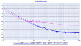
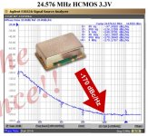
I also attach the phase noise plot of the Crystek CCHD-957 at 24.576 MHz, measured from the manufacturer using an Agilent E5052A (it uses cross correlation to measure the phase noise like the Timepod).
As you can see the phase noise plots are almost equal, the measurement from the Timepod is around 2 dB better against the E5052A. You should know that could be a difference from a crystal to another, mostly if we are talking about cheap crystal. Maybe we have got one of the best.
This means that the measurement from the Timepod is reliable, at least at 24.576 MHz.
Since the half frequency of the master clock (12.288 MHz) is still in the range of the Timepod we can assume the reliability of the FifoPi SCK phase noise measurement.
Now the jitter, as you can see the calculated jitter from the Timepod is almost the same from your digital oscilloscope, a little less than 3 ps.
We have to assume the reliability of the calculation.
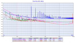
A little disgression, take a look at this link Crystek CCHD-957 | H i F i D U I N O
They have calculated the jitter with a different integration bandwidth, so the Crystek is more than an order of magnitude better, 120 fs!
What a trick!
This says a lot about the usefulness of the jitter measurement.
But if you take a look at the phase jitter per segment you see that the major contribution is in the 10 Hz region (1 Hz is missing), so you can understand the possible weight of the 6 MHz from the carrier you are pointing out, null.
Back to the topic, I forward again a few simple questions, just in cause you would kindly answer:
- the phase noise measurements of the Crystek are almost identical (Timepod vs E5052A), can you trust the measurement?
- the calculated jitter is identical, can you trust the measurement?
- what does 3 ps jitter explains?
- is 3 ps of jitter the "ultimate" performance to be reached?
- why the phase noise grows above 30 Hz from the carrier?
Please, let us know.
So you will understand the meaning of the power supply spurs and mostly what you have to care about the phase noise at 6 MHz from the carrier (half the carrier frequency).
Moreover you can play with a phase noise to jitter converter to understand that the major contribution to the jitter calculation comes from the close in phase noise and not at 6 MHz from the carrier (that weights nothing).
But as I have already pointed out, if your goal is to remove the spurs from the power supply of the Rpi then you have reached the target.
We have all understood that your real time digital oscilloscope is the reference gear to measure the jitter, so keep out for a while the RPi measurement and focus to the FifoPi SCK and master clock (Crystek) measurements.
Your FifoPi operates in a different domain then we have to assume that it was not source dependent, so the source is not relevant in the investigation.
I attach again the phase noise plot of the FIfoPi SCK vs the master clock.
I also attach the phase noise plot of the Crystek CCHD-957 at 24.576 MHz, measured from the manufacturer using an Agilent E5052A (it uses cross correlation to measure the phase noise like the Timepod).
As you can see the phase noise plots are almost equal, the measurement from the Timepod is around 2 dB better against the E5052A. You should know that could be a difference from a crystal to another, mostly if we are talking about cheap crystal. Maybe we have got one of the best.
This means that the measurement from the Timepod is reliable, at least at 24.576 MHz.
Since the half frequency of the master clock (12.288 MHz) is still in the range of the Timepod we can assume the reliability of the FifoPi SCK phase noise measurement.
Now the jitter, as you can see the calculated jitter from the Timepod is almost the same from your digital oscilloscope, a little less than 3 ps.
We have to assume the reliability of the calculation.
A little disgression, take a look at this link Crystek CCHD-957 | H i F i D U I N O
They have calculated the jitter with a different integration bandwidth, so the Crystek is more than an order of magnitude better, 120 fs!
What a trick!
This says a lot about the usefulness of the jitter measurement.
But if you take a look at the phase jitter per segment you see that the major contribution is in the 10 Hz region (1 Hz is missing), so you can understand the possible weight of the 6 MHz from the carrier you are pointing out, null.
Back to the topic, I forward again a few simple questions, just in cause you would kindly answer:
- the phase noise measurements of the Crystek are almost identical (Timepod vs E5052A), can you trust the measurement?
- the calculated jitter is identical, can you trust the measurement?
- what does 3 ps jitter explains?
- is 3 ps of jitter the "ultimate" performance to be reached?
- why the phase noise grows above 30 Hz from the carrier?
Please, let us know.
Attachments
Last edited:
@andrea_mori
Please don't change the topic.
Since you claimed everything based on your testing results, please focus on the problem of your measurements as I pointed out.
I don't want to be off topic on this thread. If you are interested in, I'd be glad to discuss with you the FifoPi principle in my thread.
You still not answer:
1. Why was your phase noise testing result incorrect for the 11.2896 MHz RPi SCK signal?
2, Both your RPi and FifoPi 192KHz LRCK phase noise results were wrong, why?
I attached the three analog waveforms of the above signals. Just make it easier to understand.
#2445
https://www.diyaudio.com/forums/dig...itter-crystal-oscillator-246.html#post6321516
#2462
https://www.diyaudio.com/forums/dig...itter-crystal-oscillator-247.html#post6321584
#2478
https://www.diyaudio.com/forums/dig...itter-crystal-oscillator-248.html#post6322697
Regards,
Ian
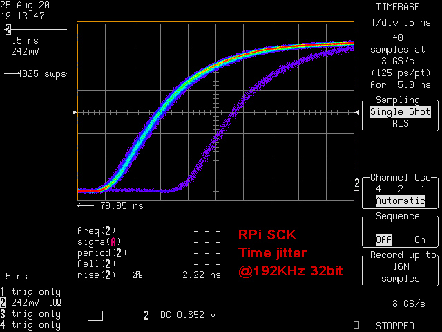
SCK_RPi_192_Direct by Ian, on Flickr

LRCK_RPi_192_Direct by Ian, on Flickr
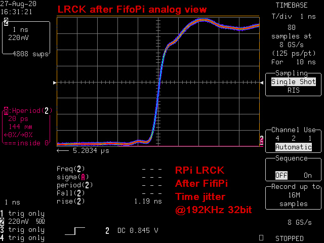
LRCKafterFifoPi192_Analog by Ian, on Flickr
Please don't change the topic.
Since you claimed everything based on your testing results, please focus on the problem of your measurements as I pointed out.
I don't want to be off topic on this thread. If you are interested in, I'd be glad to discuss with you the FifoPi principle in my thread.
You still not answer:
1. Why was your phase noise testing result incorrect for the 11.2896 MHz RPi SCK signal?
2, Both your RPi and FifoPi 192KHz LRCK phase noise results were wrong, why?
I attached the three analog waveforms of the above signals. Just make it easier to understand.
#2445
https://www.diyaudio.com/forums/dig...itter-crystal-oscillator-246.html#post6321516
#2462
https://www.diyaudio.com/forums/dig...itter-crystal-oscillator-247.html#post6321584
#2478
https://www.diyaudio.com/forums/dig...itter-crystal-oscillator-248.html#post6322697
Regards,
Ian
SCK_RPi_192_Direct by Ian, on Flickr
LRCK_RPi_192_Direct by Ian, on Flickr
LRCKafterFifoPi192_Analog by Ian, on Flickr
Last edited:
I give up.
The Timepod is not able to measure the jitter of the RPi, the only gear that can do the job is your real time digital oscilloscope.
Why?
I don't know, maybe it does not integrate the phase noise at 6 MHz from the carrier, or maybe it does not integrate the power supply spurs, or maybe its measurement method (the cross correlation) is totally wrong.
I will ask the designer.
Now, as you suggested I move the discussion around the FifoPi on your thread, indeed here we are discussing about low noise oscillators.
20/35/bs1k.png - Visionneuse Zupimages
Andrea can tell us which power supply you used for the measurement.
Andrea can tell us which power supply you used for the measurement.
Standard linear regulator and our new batteries power supply
The Well Regulated Power Supply
The Well Regulated Power Supply
- Status
- Not open for further replies.
- Home
- Source & Line
- Digital Line Level
- The Well Tempered Master Clock - Building a low phase noise/jitter crystal oscillator