@andrea_mori
1.
I don't see any jitter, I measure the phase noise, I have calculate the jitter using a converter.
As I said several time I don't care about jitter since it's a standalone number without the noise spectrum, useless for me.
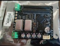
You continue arguing about LRCK, but the phase noise plot tells that you have even higher noise floor in the SCK.
For your convenience, forgive for a while the LRCK since you don't trust the measurement with the Timepod at low frequency, but you have the identical noise floor issue at a frequency (12.288 MHz) where the reliability of the Timepod is indisputable.
Can you explain the reason?
You still not answer my question "Why can't you see the 590.4ps time domain random jitter and deterministic jitter in your phase domain measurement?"
If you can not see jitter, you should see something in phase noise.
2.
Because if you change the integrating bandwidth the jitter change too.
As you can see it's an arbitrary value, while the phase noise plot is absolute, it shows exactly the noise in dB of all the sideband.
You can't argue an absolute value, while you can argue an arbitary value.
Integration bandwidth has nothing to do with my time domain measurement.
To convert phase noise plot into phase jitter, you need to integrate the full bandwidth to make it equivalent to time jitter. If the bandwidth is not enough, the calculated phase jitter number will be smaller. But in your case it is opposite, the RMS 66.19ps calculated phase jitter number was much bigger than the 7.68ps time jitter. You didn't give us any explanation.
3.
Because the noise floor of the output is very high, I suspect it's due to the crosstalk.
Why this crosstalk?
Are you using the PLL of the FPGA?
Have you took a look at the waveform before the D-FF?
What noise floor do you mean? jitter noise floor? logic level noise floor? or measurement noise floor?
I myself is an audiophile. I didn't use any PLL in FPGA. FifoPi FPGA logic is slaved to the MCLK. FifoPi is implemented in synchronized logic architecture for the best possible low jitter performance.
Clock time jitter is deviation of a clock edge from itsideal location. I suspect you convert the LRCK into sine wave before you feed into TimePod with clock edge information lost. DAC relies on edge of clock to perform conversion, not the sine wave.
You still not answer my question "The huge difference in time jitter before and after FifoPi can be directly seen from the analog waveforms, why we can not find the difference in your phase noise plot."
Good weekend.
Ian
"TimeLab does not make a distinction between random and deterministic jitter, so any spurs in phase noise plots are “integrated” as if they contained only random noise."
I have measured the phase noise not the jitter, so I cannot see the jitter while you cannot see the spectrum of the noise.
Jitter measurements are useless for me, I need to see the spectrum of the noise, so as I said everal times I have calculated the jitter using a phase noise to jitter converter.
I have not converted anything from square to sine wave, the LRCK feeds the Timepod directly (I only use 6dB attenuator in all the measurements).
Anyway, the attached plots shows the calculated jitter from the Timepod.
"Along with many other sources, HP Application Note AN270-2 provides a concise summary of the math behind phase-noise integration." (from Timepod manual, attached)
Now the question, what should we trust?
1) a real time oscilloscope with a disputable timebase and 8 bit ADCs
2) a phase noise analyzer, 3 cornered hat measurement (allows to measure a DUT better than the reference), 2 x MTI 260 OCXO as reference, cross-correlation and 4 x 16 bit 80 Smps low noise ADCs (LTC2216)
Everyone will decide what to trust.
Attachments
"TimeLab does not make a distinction between random and deterministic jitter, so any spurs in phase noise plots are “integrated” as if they contained only random noise."
I wonder how does it integrate spurs which are opressed?
Anyway, thank You Andrea. I think we are getting closer to the solution of this little 'mistery'
The distortion that I started to perceive is in here:
JITTER. !=. PHASE NOISE INTEGRATED
jitter is the total sum of all contribution: the integrated noise floor in the range of interest plus the energy in the discrete frequency spurs.
Now, I understand completely that spurs are only an annoyance, obstacle in individual oscillator quality assesment.. Oscillators are not producing discrete frequency, unwanted components.
The spurs render the integration more complicated and confusing, more difficult to calculate concrete numbers for characterisation.
But the sceen completely changes in the moment we place the oscillator in a system.
A digital system is choke full of discrete frequency noise sources, and this is the principal element..
Then these sources will find their way (through conducted or received EMI, ground loops etc) into the once clean oscillator waveform.
So on system level, a tool which is not capable to identify, in frequency and magnitude, those individual spurs, and provide a total number of final jitter with spur energy calculated..
Is useless for system debugging.
Again: it's a perfect tool for it's specific purpose, much better than any scope could be ever.
But until You cannot turn off that damn 'spur surpression' feature - it is useless for our purposes.
Ciao, George
Last edited:
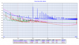
At 1,5 Hz, the non-battery is 7 dB better... to make sense these measurements maybe need some smoothing?
//
Smoothed plot, anyway you have to ideally smooth the traces, peaks can change between measurements, mostly in the close in region (1Hz).
There is a great literature on this at Rubiola.org
Attachments
I had no doubt.
Now I have to order the Jitter package for my Lecroy Wavepro 954.
Maybe I have to sell my Timepod.
Anyone interested?
Andrea,
When we will be cooled and not arguing..
You yourself will recognize that the correct, engineer's answer is: "both"
"TimeLab does not make a distinction between random and deterministic jitter, so any spurs in phase noise plots are “integrated” as if they contained only random noise."
I wonder how does it integrate spurs which are opressed?
Anyway, thank You Andrea. I think we are getting closer to the solution of this little 'mistery'
The distortion that I started to perceive is in here:
JITTER. !=. PHASE NOISE INTEGRATED
jitter is the total sum of all contribution: the integrated noise floor in the range of interest plus the energy in the discrete frequency spurs.
Now, I understand completely that spurs are only an annoyance, obstacle in individual oscillator quality assesment.. Oscillators are not producing discrete frequency, unwanted components.
The spurs render the integration more complicated and confusing, more difficult to calculate concrete numbers for characterisation.
But the sceen completely changes in the moment we place the oscillator in a system.
A digital system is choke full of discrete frequency noise sources, and this is the principal element..
Then these sources will find their way (through conducted or received EMI, ground loops etc) into the once clean oscillator waveform.
So on system level, a tool which is not capable to identify, in frequency and magnitude, those individual spurs, and provide a total number of final jitter with spur energy calculated..
Is useless for system debugging.
Again: it's a perfect tool for it's specific purpose, much better than any scope could be ever.
But until You cannot turn off that damn 'spur surpression' feature - it is useless for our purposes.
Ciao, George
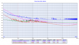
It looks like you have not understood, the Timepod integrates spurs when calculating the RMS jitter, so nothing is lost.
Simply the spurs are useless to understand jitter and phase noise, Gerhard has well explained the reasons.
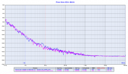
Anyway, since you are so interested on the spurs I turn off the suppression and I attach the plot with spurs.
Now you see the power supply noise (100 Hz) and its harmonics, that are totally useless.
Attachments
Andrea,
When we will be cooled and not arguing..
You yourself will recognize that the correct, engineer's answer is: "both"
I have no correct answer, my comments are ended, everyone will give himself the answer.
Andrea,
When we will be cooled and not arguing..
You yourself will recognize that the correct, engineer's answer is: "both"
True words... on the analog side of things (amplifiers filters etc.) I always work on "frequency" with my Audio Precision audio analyzer, but still wants to look with my scope at the signal shape.
For a full understanding it makes very much sense to look at frequency AND time domain
re #2508
You've got it the wrong way around.
Once you see anything bad on the scope, an oscillator
signal is already f*ed up completely.
That's why signal source analyzers were invented.
And if we still have ground bounce problems, we
have not arrived in the proper league yet.
It's step 2 after step 1. Like first connecting the
fiber properly and then measuring the neutrino speed.
And at 8 GSPS and 16 Msamples, the record length is 2 msec.
Now think for a moment if we classify 10 Hz effects
such as 1/f.
Without a picosecond time of hesitation.
The instrument which is telling me the truth.
In this specific case, the oscilloscope.
When performing Low frequency, high dynamic range Phase noise measurements - an oscilloscope is not a capable tool (they dont have the dynamic range, reference time-base stability, thermal stability or memory depth), where as the phase noise measurements systems such as the TimePod / E5052 etc. are designed for this very purpose...
Unlike earlier phase noise system, making PN measurements is child's play, and pretty much infallible... Knowing the TimePod, I suspect there's a good chance I'll confirm Andrea results, but whats more important is to understand the cause so I can get this information back to Ian.
It looks like you have not understood, the Timepod integrates spurs when calculating the RMS jitter, so nothing is lost.
Simply the spurs are useless to understand jitter and phase noise, Gerhard has well explained the reasons.
Anyway, since you are so interested on the spurs I turn off the suppression and I attach the plot with spurs.
Now you see the power supply noise (100 Hz) and its harmonics, that are totally useless.
I dont agree that you can ignore the spurs, these will impact the audio quality.
I dont believe Gerhard intentions was to say that spurie could be ignored... just that they could a result of an external signal (AC Magnet field, mains hum) not necessarily due to the oscillator circuit itself - they will however impact audio performance.
Not sure if my FifoPi is the latest version but if it is I will happily send it on Monday
Will verify with Ian.
Forane12,
Thank you, but just a warning (not sure if this is OK with you) - when working with the PCB Ill need to solder test points to help diagnose the root cause if the earlier measurements are confirmed...
Not sure you would be happy with your PCB being modified / hacked
")
- Status
- Not open for further replies.
- Home
- Source & Line
- Digital Line Level
- The Well Tempered Master Clock - Building a low phase noise/jitter crystal oscillator