This: Transmission line - Wikipedia, the free encyclopedia might help too.
Cool stuff. Thanks for the link. So maybe we should look at each power/gnd rail pair as a transmission line, too, and bang them with square waves while shortening the rise-times until they ring and then also insert a snubber at the load by following the procedure in post 292 at http://www.diyaudio.com/forums/powe...lm-caps-electrolytic-caps-30.html#post2828689 , which would basically just be a shunt resistor equal to the characteristic impedance, and an optional capacitor if the resistor's dissipation would be too high without it. I suspect it might amount to placing a small resistance in series with the decoupling cap. That should optimize (minimize) the rail-voltage fluctuations. That might be especially-useful for power rails with digital loads.
Last edited:
Cool stuff. Thanks for the link. So maybe we should look at each power/gnd rail pair as a transmission line, too, and bang them with square waves while shortening the rise-times until they ring and then also insert a snubber at the load by following the procedure in post 292 at http://www.diyaudio.com/forums/powe...lm-caps-electrolytic-caps-30.html#post2828689 , which would basically just be a shunt resistor equal to the characteristic impedance, and an optional capacitor if the resistor's dissipation would be too high without it. I suspect it might amount to placing a small resistance in series with the decoupling cap. That should optimize (minimize) the rail-voltage fluctuations.
The point is that everything is kind of transmission line and with digital consumers everything rings.
So, as many have already pointed out, there is not much sense in making PSU with very good regulation - it won't be able to see what's happening at the consumer end.
Another point is that every nasty consumer should be neutralized on the spot. That's why decoupling capacitors as close to pins as possible.
That's why distributed regulators. There are linear regulators in TO-92 cases, and they are cheap.
The whole issue of grounding topology is voodoo. There are different schools/approaches, and they all make sense in some respects and less sense in others. I once spent about a week on what ended up as an additional pretty thick wire about 3cm long connecting two ground points on a PCB. Electrically there was no missing connection, simply those two points needed smaller impedance. The circuit was digital, by the way.
I again suggest stepping on rakes of made from scratch switching power supply. Really deflates overhyped optimism and belief in simulations.
...
See my posts in another thread - for the links in the posts: http://www.diyaudio.com/forums/digi...e-regenerated-usb-power-line.html#post3062906 , http://www.diyaudio.com/forums/digi...e-regenerated-usb-power-line.html#post3062942 .
...
Whatever ...
The point is that everything is kind of transmission line and with digital consumers everything rings.
I'm with you.
So, as many have already pointed out, there is not much sense in making PSU with very good regulation - it won't be able to see what's happening at the consumer end.
Unless it were placed right AT the load. But otherwise, even if it could somehow see what happened at the consumer end, it couldn't do much about it.
Another point is that every nasty consumer should be neutralized on the spot. That's why decoupling capacitors as close to pins as possible.
I have been preaching about decoupling capacitors, and have been emphasizing the need to place them close-enough to pins, in order to meet allowable inductance/impedance requirements, for quite a while now, but more in terms of trying to be able to perfectly-satisfy the current demands of the nasty consumers so that they can do their jobs well, with neutralizing their effects on the rail voltage as just another constraint driving the low-inductance/impedance (i.e. distance from pins) requirement.
That's why distributed regulators. There are linear regulators in TO-92 cases, and they are cheap.
I'm totally with you on the idea of distributed regulators. Moving everything to (or re-doing at) each active point of load solves a lot of problems.
(But) I have also been trying to think about applying these ideas to improving the accuracy of the response of high-current active audio amplification devices, and would probably like to investigate at least to the edge of overkill. Just thinking out loud, maybe in addition to actually calculating proper decoupling placement and value requirements, I should start thinking about adding some volts to the main PSU output level, and calling it a pre-regulator, and using a compact high-current regulator (like TO-220) just before each consumer's decoupling capacitors, probably with another reservoir cap just before the regulator. (As a side-effect, that might also be one good way to keep the AC junk well-away from all small-signal portions of the circuit.)
The whole issue of grounding topology is voodoo. There are different schools/approaches, and they all make sense in some respects and less sense in others. I once spent about a week on what ended up as an additional pretty thick wire about 3cm long connecting two ground points on a PCB. Electrically there was no missing connection, simply those two points needed smaller impedance. The circuit was digital, by the way.
I have been thinking that I no longer like the way the concept of ground is typically used. It seems to muddy the potential for understanding. There is no zero volts. All voltages are only relative to somewhere else. Ground points and ground rails should probably be viewed the same way as the power rails. With dynamic currents, both have voltage fluctuations everywhere, relative to everywhere else, anyway, unless distances are zero.
I again suggest stepping on rakes of made from scratch switching power supply. Really deflates overhyped optimism and belief in simulations.
"Stepping on rakes"? Do you mean like when one steps on the tines of a stiff-and-short-tined rake that's leaning up against something, and the rake's handle slams into one's face or head, "rather immediately"? I did that once. It "gets your attention" (after your senses return, if you're not dead <grin>).
It seems weird to me that many people use simulations with ideal models of everything, and then don't seem to take that fact into account. However, simulations can be made as accurate as desired, if the models can be made as accurate as desired. But, knowing if that is possible, and knowing how to do it, and deciding if it is worth doing or to what extent, and actually doing it, and understanding its limitations and error margins, can all be very difficult.
I have designed a few switchmode power supplies, back when I knew even less than I do now. Ideal simulations once showed output noise of something like 20 microvolts, which was only wrong by a factor of 10000 or so.
...
See my posts in another thread - for the links in the posts: http://www.diyaudio.com/forums/digi...e-regenerated-usb-power-line.html#post3062906 , http://www.diyaudio.com/forums/digi...e-regenerated-usb-power-line.html#post3062942 .
I've read the posts. Will investigate the links. Thanks!
...
Whatever ...
Thanks for engaging. I will have to chew on all of this for a while.
...........The whole issue of grounding topology is voodoo. There are different schools/approaches, and they all make sense in some respects and less sense in others.
I'm also with you. I have been preaching that the use of the all encompassing word "Ground" leads many to complete confusion.I'm with you.........................
I have been thinking that I no longer like the way the concept of ground is typically used. It seems to muddy the potential for understanding. There is no zero volts. All voltages are only relative to somewhere else. Ground points and ground rails should probably be viewed the same way as the power rails. With dynamic currents, both have voltage fluctuations everywhere, relative to everywhere else, anyway, unless distances are zero.
Just about every "ground" is actually the return route for a flow current. Each Ground route is part of a circuit.
If everyone were to refer to grounds as specific circuits much of the "Voodoo" would disappear.
As an example, I repeatedly refer to Signal Ground and/or Power Ground and/or Speaker Return and/or PSU Zero Volts, etc. to help avoid that confusion, in my posts and for the readers.
Last edited:
I'm with you.
Unless it were placed right AT the load. But otherwise, even if it could somehow see what happened at the consumer end, it couldn't do much about it.
I have been preaching about decoupling capacitors, and have been emphasizing the need to place them close-enough to pins, in order to meet allowable inductance/impedance requirements, for quite a while now, but more in terms of trying to be able to perfectly-satisfy the current demands of the nasty consumers so that they can do their jobs well, with neutralizing their effects on the rail voltage as just another constraint driving the low-inductance/impedance (i.e. distance from pins) requirement.
I'm totally with you on the idea of distributed regulators. Moving everything to (or re-doing at) each active point of load solves a lot of problems.
(But) I have also been trying to think about applying these ideas to improving the accuracy of the response of high-current active audio amplification devices, and would probably like to investigate at least to the edge of overkill. Just thinking out loud, maybe in addition to actually calculating proper decoupling placement and value requirements, I should start thinking about adding some volts to the main PSU output level, and calling it a pre-regulator, and using a compact high-current regulator (like TO-220) just before each consumer's decoupling capacitors, probably with another reservoir cap just before the regulator. (As a side-effect, that might also be one good way to keep the AC junk well-away from all small-signal portions of the circuit.)
I have been thinking that I no longer like the way the concept of ground is typically used. It seems to muddy the potential for understanding. There is no zero volts. All voltages are only relative to somewhere else. Ground points and ground rails should probably be viewed the same way as the power rails. With dynamic currents, both have voltage fluctuations everywhere, relative to everywhere else, anyway, unless distances are zero.
"Stepping on rakes"? Do you mean like when one steps on the tines of a stiff-and-short-tined rake that's leaning up against something, and the rake's handle slams into one's face or head, "rather immediately"? I did that once. It "gets your attention" (after your senses return, if you're not dead <grin>).
It seems weird to me that many people use simulations with ideal models of everything, and then don't seem to take that fact into account. However, simulations can be made as accurate as desired, if the models can be made as accurate as desired. But, knowing if that is possible, and knowing how to do it, and deciding if it is worth doing or to what extent, and actually doing it, and understanding its limitations and error margins, can all be very difficult.
I have designed a few switchmode power supplies, back when I knew even less than I do now. Ideal simulations once showed output noise of something like 20 microvolts, which was only wrong by a factor of 10000 or so.
...
I've read the posts. Will investigate the links. Thanks!
...
Thanks for engaging. I will have to chew on all of this for a while.
Gootee,
I think there is a little confusion in this thread.
I start the thread in parallel to Ian's thread, but as I said in first post I'm trying to build a regulated power supply either suitable for digital than analog audio circuits, not specifically for Ian's FIFO buffer.
My primary goal is to use it to supply analog stage of PCM63 DAC.
I try to design a regulated power supply, both positive and negative rail, from 4.5V to 28V output voltage: good regulation, low drift, low noise, low output impedance.
So I can't see it as a system. In the case of Ian's project, he has to solve local supply problems, with adeguate decoupling at the load.
I could only try to build a good PSU.
Then it could be used as a distributed regulator. I'm planning to use several for my DAC conversion: 1 for Ian's FIFO buffer (separate supply for clock), 1 for digital filter (SM5842) and digital section of PCM63, 2 for analog section of PCM63 (positive and negative) , 2 for output buffer (unless I'll use a tubes stage).
I could provide a Kelvin connection, but not certainly with a delay circuit. Your idea is right about delay, but it's not really implementable.
As I said in a previous post, simply adding 2 capacitors closely to the drain of the output devices of a power amp the result changed drastically. So, I think starting from a good enough supply regulator, sometimes it will be sufficient decoupling the load with film capacitor as closest as possible to the load itself.
Simulations, for me, are the starting point to design, then prototyping and real measures.
But maybe I'm wrong.
Andrea
I believe one must design the system.
I have many times in the past told Members that adding a regulated PSU to a Power Amplifier is not a simple addon process.
The proposed "system" must be designed to operate as "one".
I'm not designing a regulated PSU for a power amp, but only for low current digital and analog audio circuit.
I agree with you that the best solution is to design entire system, but sometimes is not possible.
Ian provide FIFO board without power supply, so I have to get a power supply for that.
Also I would build my own DAC and I need to supply it.
I do not agree about who said "local simple monolithic 3 terminals regulator are the best solution". Many years ago I built a DAC to use in my car with CS8412/CS4329, nothing of exceptional, and I provide supply with monolithic IC regulator, 1 for each load: the result was bad. Then I revised the project using IC 3 terminals regulator as pre-regulation, adding a cascade stage composed of a voltage reference (AD580), an opamp (AD797) and a D44VH10 as the pass device. The sonic result changed much, and with a low cost DAC as CS4329 final result was more than acceptable.
Andrea
I know, I was quoting an exampleI'm not designing a regulated PSU for a power amp,
This is your example of "addon" going wrong and "system design" taking over............ Many years ago I built a DAC to use in my car with CS8412/CS4329, nothing of exceptional, and I provide supply with monolithic IC regulator, 1 for each load: the result was bad. Then I revised the project using IC 3 terminals regulator as pre-regulation, adding a cascade stage composed of a voltage reference (AD580), an opamp (AD797) and a D44VH10 as the pass device. The sonic result changed much, and with a low cost DAC as CS4329 final result was more than acceptable.
I know, I was quoting an exampleThis is your example of "addon" going wrong and "system design" taking over.
We have two different point of view: I see that as "the first addon, the 3 terminals monolithic regulator, going wrong; the second addon, the improved regulator, going well".
Finally, the problem is the supply regulator, not the system, considering it supplies the same client.
Then, starting from a good regulator is a good starting point to get good result at system level.
Andrea
I
...
"Stepping on rakes"? Do you mean like when one steps on the tines of a stiff-and-short-tined rake that's leaning up against something, and the rake's handle slams into one's face or head, "rather immediately"? I did that once. It "gets your attention" (after your senses return, if you're not dead <grin>).
...
That is exactly what I mean.
Gootee,
I think there is a little confusion in this thread.
I start the thread in parallel to Ian's thread, but as I said in first post I'm trying to build a regulated power supply either suitable for digital than analog audio circuits, not specifically for Ian's FIFO buffer.
My primary goal is to use it to supply analog stage of PCM63 DAC.
I try to design a regulated power supply, both positive and negative rail, from 4.5V to 28V output voltage: good regulation, low drift, low noise, low output impedance.
So I can't see it as a system. In the case of Ian's project, he has to solve local supply problems, with adeguate decoupling at the load.
I could only try to build a good PSU.
Then it could be used as a distributed regulator. I'm planning to use several for my DAC conversion: 1 for Ian's FIFO buffer (separate supply for clock), 1 for digital filter (SM5842) and digital section of PCM63, 2 for analog section of PCM63 (positive and negative) , 2 for output buffer (unless I'll use a tubes stage).
I could provide a Kelvin connection, but not certainly with a delay circuit. Your idea is right about delay, but it's not really implementable.
As I said in a previous post, simply adding 2 capacitors closely to the drain of the output devices of a power amp the result changed drastically. So, I think starting from a good enough supply regulator, sometimes it will be sufficient decoupling the load with film capacitor as closest as possible to the load itself.
Simulations, for me, are the starting point to design, then prototyping and real measures.
But maybe I'm wrong.
Andrea
Sorry.
Have you made any more progress on settling the opamp questions?
...
Simulations, for me, are the starting point to design, then prototyping and real measures.
But maybe I'm wrong.
Andrea
I think you are wrong.
Starting point of design is quick assessments in one's head or "on the back of an envelope". And rejecting obviously wrong things - like one may think 1H real life choke + 1F real life capacitor comprising an LPF will have excellent ripple rejection at 1MHz.
Another story. As a CAD engineer I was working as small part of a big team on a CPU. I was helping for a couple of weeks a design engineer to verify his block, using state of the art commercial and in-house SW - quite advanced.
After completion the design engineer said that after couple of months of work his design changed about 10% (he meant values of components, like R, C, transistor sizes) from the initial quick paper + pencil sketch.
I think too much love for simulators with almost disabled design by brain is a massive illness among modern younger engineers.
But don't get me wrong - I was responsible for designing simulation environments for digital simulations and I ran a number of analog simulations in HSPICE, which I managed to pretty quickly crash, so as a workaround I had to change stimuli ...
Sorry.
Have you made any more progress on settling the opamp questions?
For the series regulation I choose AD797, I got excellent results in my previous experience in supply regulation.
About shunt stage I cannot find a suitable opamp, low input bias current, low noise, adeguate transconductance.
But as I said in a previous post I don't like shunt regulation and I think series regulation is more than sufficient, so I think to eliminate this stage.
I think you are wrong.
Starting point of design is quick assessments in one's head or "on the back of an envelope". And rejecting obviously wrong things - like one may think 1H real life choke + 1F real life capacitor comprising an LPF will have excellent ripple rejection at 1MHz.
Another story. As a CAD engineer I was working as small part of a big team on a CPU. I was helping for a couple of weeks a design engineer to verify his block, using state of the art commercial and in-house SW - quite advanced.
After completion the design engineer said that after couple of months of work his design changed about 10% (he meant values of components, like R, C, transistor sizes) from the initial quick paper + pencil sketch.
I think too much love for simulators with almost disabled design by brain is a massive illness among modern younger engineers.
But don't get me wrong - I was responsible for designing simulation environments for digital simulations and I ran a number of analog simulations in HSPICE, which I managed to pretty quickly crash, so as a workaround I had to change stimuli ...
Obviously I start from a basic idea, as I said in my first post: CRC passive filtering, opamp based regulation, hi-grade components.
Also many other starting points was clear in my head before circuit simulation, for example:
- use a feedback control circuit opamp based rather than a simply 3 terminals IC monolithic regulator
- use a transistor (not a mosfet) as the pass device, or better use D44H11/D45H11 for its linearity
- use an ultra low noise opamp as feedback control device
- use a ballast resistor to load regulator as about client load
- use film capacitors where possible, bypass electrolityc capacitors with film capacitors in some points of the circuit
- paralleling electrolityc capacitors rather than use a single capacitor
- use metal foil resistors, or at leat wirewound resistors
- use a low noise, low drift bandgap as reference for the feedback circuit
- supply active device from regulated output where it's possible
This is the basic idea in my mind, then I use simulation to analyze and tuning.
Final tuning at prototype level.
So, I meant simulation is a good starting point, but obviously following a solid basic idea.
Revision
Some changes:
- filtering section now is a CRCRC, also resistors value increased from 1 to 1.8 ohm
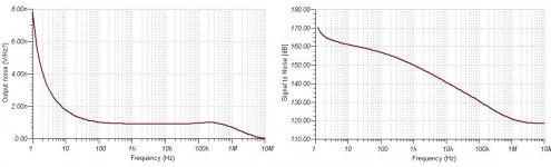
- now use a low noise voltage reference composed of LT1009 filtered and buffered by MAX9632 opamp. Its teorically output noise is less than 2 nV/sqrt(Hz).
- shunt section removed
- paralleled some critical capacitors
Andrea
Some changes:
- filtering section now is a CRCRC, also resistors value increased from 1 to 1.8 ohm
- now use a low noise voltage reference composed of LT1009 filtered and buffered by MAX9632 opamp. Its teorically output noise is less than 2 nV/sqrt(Hz).
- shunt section removed
- paralleled some critical capacitors
Andrea
Attachments

http://www.ti.com/lit/an/slva255/slva255.pdf - hopefully will open some eyes around here.
http://www.ti.com/lit/an/slva255/slva255.pdf - hopefully will open some eyes around here.
interesting.. but I don't understand the connection...
the article is about switching converter, while I'm designing a linear regulator.
Obviously I could have issue about parasitic inductance and capacitance at pcb layout level, but now I'm still far from pcb designing.
Andrea
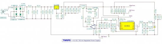
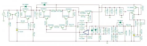
Ready to breadboard
After several changes this is the final schematic I'm going to prototype:
- 3 terminal pre-regulator was replaced by a discrete pre-regulation, because IC regulator has serious problem of output impedance at low frequencies. Now a TL431 act as feedback control amplifier and drives a Sziklai pair pass transistor. T1 and T2 act as a CCS to flow the right current through the TL431
- another TL431 works as voltage reference feeded by another CCS (T11 and T12). Reference voltage is set around 10V then is divided by 10 and filtered by a first order low pass filter, so the noise is drastically reduced
- the AD797 operates as the feedback loop control of the series regulator. Its gain bandwidth was reduced to avoid oscillation
- T10 act as a gyrator to provide a more clean supply to AD797 and voltage reference stage
- the pass device of the series regulator use a push-pull Sziklai pair to get a very low output impedance. A quiescent current flow through the push-pull even without any load.
- all capacitors now have its real ESL, ESR and leakage current
Now I'm going to order parts to try and test the regulator with a breadboard.
Andrea
Attachments
- Home
- Amplifiers
- Power Supplies
- The Well Regulated Power Supply