When youdid the volume pot noise tests, Did you leave the amplifier input impedance at normal value or short the amplifier input to ground?
Post#4, the same for all preceding simulations.
Attachments
Last edited:
Well 9 pages plus of reading and all I've got out of it is that the frequency range used for the noise calcs is still a problem in the discussions, not on the wide side as suggested in several posts, but on the narrow side.
Requirement spec in the first post or two was +/- 5 degrees phase shift in the 20Hz to 20kHz band.
Haven't done the exact math on that phase shift specification but that suggests to me a -3dB bandwidth of say 2Hz to 200kHz.
The guitar amp post was a bit of a "red herring", in nearly all guitar amps, the most significant source of noise is the 68K grid stop resistor on the input tube. One of those cases of an original designer screwing up and then that screw up being copied by even less adequate designers ever since. In my experience Tube HiFi is slightly less prone to that but it is certainly not free of it.
Cheers,
Ian
Poplin (and others who are interested),
The complete pdf is available on the pearl web site :
http://www.pearl-hifi.com/06_Lit_Ar...apers/Vogel_Burkhard/The Sound of Silence.pdf
The complete pdf is available on the pearl web site :
http://www.pearl-hifi.com/06_Lit_Ar...apers/Vogel_Burkhard/The Sound of Silence.pdf
Well 9 pages plus of reading and all I've got out of it is that the frequency range used for the noise calcs is still a problem in the discussions, not on the wide side as suggested in several posts, but on the narrow side.
Requirement spec in the first post or two was +/- 5 degrees phase shift in the 20Hz to 20kHz band.
Haven't done the exact math on that phase shift specification but that suggests to me a -3dB bandwidth of say 2Hz to 200kHz.
No, it is a misinterpretation, let me explain
If you read more carefully, general design goals are
When designing a Preamp only remains for us, as design goals, the basic and standard
a) Low distortion, preferably predominantly second harmonic (the lesser evil)
b) Good dynamic response.
c) Good bandwidth.
d) Small phase shift.
e) Low output impedance.
f) Low noise.
For a particular case
1.- A traditional approach
Input => Pot => CC + CF => Output
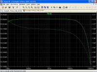
i) Phase shift
As a reasonable design goal, is expected +/- 5º phase shift from 20Hz to 20KHz.
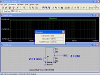
The worst case regarding the pot is at half the resistance, ie 50K + 50K when the output impedance reaches a maximum, supposing an ideal source of Z=0 ohm.
The only valve that I know for this requisite and a reasonable low gain is the ECC82/12AU7.
In the first simulation can be seen that hardly achieve +/- 5º phase shift.
ii) Noise
Meanwhile, the thermal noise produced by the pot over a range from 10Hz to 100KHz is 6.4µV RMS (second simulation).
For a tipical gain of 22dB, at the output the noise is about 80µV RMS (third simulation), only due to the pot !
For the proposed approach
3.- Another approach
Input => CC => Pot => CF => Output
i) Phase shift
In the fourth simulation we can see that the goal of +/- 5º is easily achieved over a range from 10Hz to 100KHz.
Not bad, right?
ii) Noise
In the fifth simulation, we see that now the output noise is about 7µV RMS !
Remember that the volume pot is not the only source of noise, neither the only resistor, and mathematical models of valves don't take noise into account.
However not a bad result...
Simulations are placed on the correct order, however should be placed separately to illustrate each particular point and avoid future confusion and complains.
Let me clarify that I always do simulations on the 10 Hz - 100 KHz range, so first simulation should be
But the point to illustrate became obscure now, for the scale factor.
The guitar amp post was a bit of a "red herring", in nearly all guitar amps, the most significant source of noise is the 68K grid stop resistor on the input tube. One of those cases of an original designer screwing up and then that screw up being copied by even less adequate designers ever since. In my experience Tube HiFi is slightly less prone to that but it is certainly not free of it.
Cheers,
Ian
I am not interested on guitar amps, so no comments.
Attachments
Last edited:
Poplin (and others who are interested),
The complete pdf is available on the pearl web site :
http://www.pearl-hifi.com/06_Lit_Archive/14_Books_Tech_Papers/Vogel_Burkhard/The%20Sound%20of%20Silence.pdf
Thank you very much !
I already have it, and second edition is even better, but I must to be satisfied with this.
Last edited:
For a full treatment of noise in tubes, including flicker noise, I would recommend chapter 8 of 'Amplifying Devices and Low Pass Amplifier Design' by E.M. Cherry and D.E. Hooper. Copies are expensive and hard to come by so I would recommend getting your local library to obtain a copy for you.
Cheers
Ian
Fortunately, freely available now via internet. Otherwise, some $670US!
Fortunately, freely available now via internet. Otherwise, some $670US!
Here it is:
https://archive.org/details/CherryHooperAmplifyingDevicesAndLowPassAmplifierDesign1968RR
I am pleased this book is now freely available. Hopefully it will finally put to rest the myth that the audio noise in a triode is no more than 2.5/gm.
I am not pleased this book is now freely available because I paid £67 for a copy a few years ago and it is now worthless.
Cheers
Ian
Downloaded !
Thanks a lot !
popilin, your tests have been very interesting. I am going to try a 12AX7 preamp set to a gain of 8 in front of the 250k log pot in my pioneer SX - 3700.
Then I will shunt the output with a 150k to 33k resistor with the amp being fed off the 33k.
It looks like the noise should be down by about 13 db.
Then I will shunt the output with a 150k to 33k resistor with the amp being fed off the 33k.
It looks like the noise should be down by about 13 db.
Thermal noise
Measuring/calculating the thermal noise of an ideal resistor over 10 Hz - 100 kHz vs. 20 Hz - 20 kHz: the noise spectrum is the same. You only measure/calculate over different part of it, so you get different RMS voltage. If your hearing covers say 40Hz to 12 kHz, you hear less part of it (not talking about the filtering contour of human hearing aka Robinson-Dadson curve).
Measuring/calculating the thermal noise of an ideal resistor over 10 Hz - 100 kHz vs. 20 Hz - 20 kHz: the noise spectrum is the same. You only measure/calculate over different part of it, so you get different RMS voltage. If your hearing covers say 40Hz to 12 kHz, you hear less part of it (not talking about the filtering contour of human hearing aka Robinson-Dadson curve).
You do realize, I hope, that your spice simulations of noise does not include the noise from the vacuum tubes, unless you have done something special that I have not seen yet. Those spice models of vacuum tubes do not include their noise. Please see the vacuum tube spice models thread at the top of this forum. So, all you're modeling is resistor noise right now.
Measuring/calculating the thermal noise of an ideal resistor over 10 Hz - 100 kHz vs. 20 Hz - 20 kHz: the noise spectrum is the same. You only measure/calculate over different part of it, so you get different RMS voltage. If your hearing covers say 40Hz to 12 kHz, you hear less part of it (not talking about the filtering contour of human hearing aka Robinson-Dadson curve).
Totally agree, I am bad with words but I tried to say it metaphorically
for me the standard audio range is from 10Hz to 100KHz.
This is due to the fact that there are MC cartridges arriving at 70KHz and very good tweeters too.
Hear it or not, the noise is there, the listening experience is more complex than we would like.
I can not either see the background radiation of the universe, but there are people who it bothers.
Maybe a 100 KHz bandwidth would be questionable, however, if I want to make a preamplifier with a 100 KHz bandwidth, I must integrate noise density over a 100 KHz interval. AFAIK
Last edited:
Hi,
If you want to do away with volume pots altogether you could set the volume using a valve.
Not sure if that's going to be any quieter though....
Ciao,
You do realize, I hope, that your spice simulations of noise does not include the noise from the vacuum tubes, unless you have done something special that I have not seen yet. Those spice models of vacuum tubes do not include their noise. Please see the vacuum tube spice models thread at the top of this forum. So, all you're modeling is resistor noise right now.
Post#1
Remember that the volume pot is not the only source of noise, neither the only resistor, and mathematical models of valves don't take noise into account.
My Tarzan-English doesn't help, but I think is at least understandable.
BTW, valve noise was already taken into account for most calculations.
Last edited:
OK, then I hope you realize that your spice models have limited utility when it comes to modeling circuit noise. Generally, it's best to use the lowest value potentiometer (or resistor) that you can get away with in any particular circuit if you want to minimize noise. Allowing a gain stage to be exposed to the full input voltage from a source such as a CD player is bad engineering practice because the distortion will be far higher and there is the potential for overloading the gain stage. This is why the volume control is at the front of the preamp.
In theory, you could have limited control over the gain of the input stage by having switched cathode and plate resistors, but that's not the normal practice and the results will probably be less than ideal.
It's also possible, in theory, to use a frequency compensated stepped attenuator, as is done in traditional analog oscilloscopes. That would be complicated though.
Also, flicker noise in vacuum tubes has been mathematically solved recently. There's a thread on that in this forum. So, now it's possible to model flicker noise in vacuum tubes. Someone just has to work out the code.
I know about that thread, but unfortunately, in addition that I am poor, I have no credit card, so Merlinb's pdf is out of my scope.
However flicker noise prediction, must also predict factory room conditions. AFAIK
Morgan Jones also makes clear in his "Valve Amplifiers" third edition, at page 534 sic "Unfortunately, there is no way of predicting flicker noise for a valve as it is highly sample dependent, although its level is directly related to the level of thermal noise for a given valve".
You'll have to talk to Merlin about whether or not "factory conditions" plays a large enough role to invalidate his equations. I have the article but I don't have time to find a particular reference to this issue in there right now.
Also, don't take everything you read in a book as gospel. Use your head and question everything. Authors are merely people who were able to convince a publisher that their work was worthy of publication. It does not mean that everything they say in their work is the absolute truth, or the be-all, end-all of discussion about the subject.
Also, don't take everything you read in a book as gospel. Use your head and question everything. Authors are merely people who were able to convince a publisher that their work was worthy of publication. It does not mean that everything they say in their work is the absolute truth, or the be-all, end-all of discussion about the subject.
Last edited:
- Status
- This old topic is closed. If you want to reopen this topic, contact a moderator using the "Report Post" button.
- Home
- Amplifiers
- Tubes / Valves
- The volume pot - The hidden villain of preamp