It's been said at least 3-4 times in this thread already, even though many subsequent corrections were needed. Who is going to pay all the board purchasers back after a rushed and untested board goes to production?????
NagysAudio??????
I bet Nagys could afford to do so given he sells enough of his snake oil filled vodoo cables - e.g. 140$ for 0,5m RCA cable.

I'll help and do a bit advertising for him:
Nagys Audio - Products - Provider of High End Audio Interconnect Cables
One thing Nagys and Goldmund have in common is extremely overpriced products. They both sell snake oil and both take a lot of money for it. I bet Nagys models hisself on Goldmund. Guldmund was very successful with this kind of business and maybe Nagys will be as well.
First of all, the board was done. But now the protection circuit will be incorporated in the main board. So... We have to fix a few things. It's almost done.
I said many times before, I can be the first to purchase and prototype. But I also don't think that's necessary. This is a simple amplifier and should have no problem working correctly as long as there's no mistakes in the schematic to PCB transfer.
All this nonsense about taking negative feedback from a certain special magical, low current point, or star ground, or having the input stage ground separated from the power ground, etc. is just that, nonsense.
Spind - As for your comment, I think you've lost your mind to even suggest that.
Lee Knatta - That is a personal attack. If you don't want to build this amplifier please go away. You won't be missed. We don't need your uninformed opinions confusing potential builders here. Are you an engineer? I seriously doubt it.
Your comments regarding grounding and negative feedback have more snake oil than half the audiophile community combined.
Your comments regarding grounding and negative feedback have more snake oil than half the audiophile community combined.
Yeah!... that's it!..... well Nagysaudio.... you deserve
congratulations..you have courage...you have faced the buggers....you stand up to figth, you have a sucessfull thread... you're showing us confidence, enthusiasm and hard work.
Your thread, that started a few weeks ago, is having enormous quantity of hits..you're the champion between the champions.
Naturally you gonna have strong negative energy pointed to you, some guys cannot tollerate you're doing fine... i see you are a warrior and ready for combat...i like that....yeah...i like that!
You know... someone told me the pig had enormous object to show to the girl pigs...others had so much envy, the big object turn alike the way it is... short and twisted alike a tool to remove cork from wine bottles.
It is very complicated to be sucessfull...so...be ready for envy in big packages...they will put doubt in all your decisions to push the carpet below your feet..but be sure..they are few guys..just exceptions..the big majority appreciates you.
Your input will be considered wrong, unless you do the way they want..also the output, also the VAS, also your supply..well.... some guys will never be happy and will try to unstabilize you to be nervous..to send them to the place they should never got out.. to be punished, and them to have your thread damaged..be sure they will be trying that.
Needing help...ask uncle Charlie and we gonna figth together.... in perfect harmony.... to be wounded in combat is terrible first time..second and third is easier.
If people shows that will build or are building your amp.....them give them attention..if not
The idea is to provocate, to unstabilize you.... to drive you mad..then you will spit fire and moderators will punish you because they do not accept clear offenses..but to be pushing the carpet below your feet is acceptable in their minds (non clear offenses..may be challenges in the place of offenses)... the old say " you need a thick skin" will be appliable...i think we need much more...an armour alike an armadillo..... but better is to have a sledge hammer.
I have not read the entire thread...maybe i'm wrong..but seems to me you have several clear qualities..may have some defects alike everybody have.
regards,
Carlos
Last edited:
Nagys,
Lee has brought some important points regarding grounding which you dismiss or fail to understand which probably means that you are not truely a qualified engineer but some sort of technician or hobbyist masquerading as an engineer.
If you were a real engineer, you would understand his reasoning, OS and I have pointed out the same thing about the importance of grounding,which you claim is snake oil. Pklease quote the relavent texts to prove this is so.
Regards,
Jam
Last edited:
Jam - This thread is about the best sounding amplifier (in my opinion), which is Goldmund Mimesis 6, Mimesis 3, and Mimesis 9.2. Goldmund connects ALL ground points to the ground plane. It's very simple to build this way and it sounds amazing. Goldmund amps spec extremely well, low noise and low distortion. If we are building more, or less a Goldmund clone, then lets build a clone. Why drastically alter the circuit and grounding scheme? Why ruin the magical Goldmund sound?
Can star ground perform better? Maybe... Can separatting input and power grounds help achieve a better performance? Maybe... One thing for certain is that the ground plane method will work 100% properly and is easy to build/implement. Once you start running all these thin ground traces, that's where noise/hum issues come into play. Ground plane is a no brainer, everything else can potentially require prototyping/testing to see what grounding scheme works best.
These are pure myths:
Negative feedback has to be taken from a certain point.
AC cannot be on the same board as DC due to noise.
Must have separate input ground and power ground.
Must have star ground.
Goldmund does ground plane, lets stick with that. This is a simple DIY kit and should stay at that.
Nagys,
Almost every point you make is false, star grounding might be the ultimate when general grounding is applied but usually does not apply to the input.
Judging what you say you, you make some points that are totally irrational to an engineer. You can improve the S/N raito of the amp with a few changes as suggested.
Please state your qualifications and stop beating around the bush, if you are not an engineer say so.
Hint. Ask yourself this question...When is a ground not a ground.
Regards,
Jam
The section below taken from Ben Duncan's book "High Performance Audio Power Amplifiers" will illustrate my point on how wrong Nagys is on layout and grounding considerations .......................
Power stage, critical layout requirements
The physical layout or topography of parts and hence wiring, can have a far greater
effect on signal purity and proper operation in power amplifiers, than in other audio
equipment. Poor layout causes inter-stage feedthrough or backtalk, which cause
various kinds of distortion, and even RF oscillation.
Caused by instantaneous signal voltage difference, such backtalk or feedthrough
may readily be well guarded against – if not by spacing, then with conventional
‘electrostatic’ shielding, e.g. shielded wires and any, even very thin, metal bulkhead.
The scope for voltage differences in adjacent circuitry is in any event relatively
limited −few power amplifiers have voltage gains much above 100x, and
with most, gain is nearer to x20 to x30.
Where power amplifiers differ from nearly all other audio equipment is that peak
output currents range into tens of amperes. With a high input impedance, the input
current, for tens of output amperes, may be as little as 1A. So current gain can be
over a million times. Without a well designed physical layout, there is far greater
scope for the induction of hostile signals by this route, notwithstanding that incoming
signal voltages may be at a comparatively high line level. For example, when
current differences of a million-fold exist within a few inches (millimetres even!) of
one another, the interfering magnetic field induced, or set up by the larger current is
far, far harder to shield against, than the electric field caused by a large voltage. To
be at all effective, only thick steel or far better, thinner but much more expensive
mu-metal will do. These are brute-force techniques, that are not often seen in practice.
Instead, induced current backtalk is lessened in well engineered designs by
three low cost, elegant means.
First, by keeping the high current conductors as far as possible from sensitive parts
of the driver circuitry −as magnetic field intensity falls off rapidly with distance.
Second, by minimising the area and length in particular, of sensitive nodes. Generally,
these are parts of the circuitry where the signal is in the form of current. In
nearly all cases, these are the inverting input of the driver stage (assuming conventional
global NFB) and the input differential pair’s collector nodes. The same points
are no less sensitive when an IC op-amp is employed instead of discrete circuitry −
but at least they then start out highly miniaturized, thus compact. The designer need
then only keep the -ve input’s nodal tracking compact.
Third, the radiated field is reduced further by keeping the area of high current loops
to a minimum. This may be achieved by arranging PCB tracks so the current return
is parallel and close, and by twisting high-current conductors, into send/return pairs.
A good sign this has been done properly is to look for pairs of twisted wires. A third
wire is almost certainly out of place unless it is twisted in the opposite direction.
Even better than twisting is to use audiograde cables which employ various proprietary
techniques to maximise mutual inductance and retard skin-effect. Such low
inductance cables are self-shielding. PCB tracks cannot be twisted but can be arranged
back-to-back for least series inductance. Altogether, these steps can attenuate
the voltages or currents caused by the induced magnetic field(s) by up to 60dB,
or 1000 times, or more.
Jam
Last edited:
If you want to go further.................
Critical nodes
A node is a point where different currents either originate and split-out from, or
converge at. Every junction between more than two parts in an electronic circuit is
a node. In power amplifiers, the critical nodes are those where dirty and clean, and/
or small and large signals come together. Why critical ?
Interaction
between high and low level signal currents can occur independently of
magnetic or electrostatic induction − by superimposition. This happens when ‘common’
connections to which both high level, possibly ‘dirty’, and small (and possibly
clean) signal connections have significant common length and hence resistance
This may be called bad noding. If 1 ampere flows in a 1" long connection with 1
milliohm of resistance, there will be (1.0A x 1.0 mΩ) volts, i.e. 1mV, across the
connection. If a low level signal shares this, 1mV of noise in series may be rather
large by comparison. If it is anything more than 100,000th of (or −100dB below)
the small signal, sonic degradation is possible. 1mV is therefore on the threshold of
affecting even a 60v rms large signal, let alone all the other, mainly far smaller
signal voltages, that are at large in a power amplifier. In turn, considerable nonlinearity
in audio power amplifiers may be attributed to layout. One investigator
writes “having examined ... (class B) power amplifiers I feel that this effect is the
most widespread cause of unnecessary distortion”
I suggest that if that if you want to learn more, buy the book........there is a lot good information in it.
So where is the snake oil now?
Jam
P.S. On a lighter note
YouTube - Darth Vader Plays Golf
Last edited:
Magic Grounding
All this nonsense about taking negative feedback from a certain special magical, low current point, or star ground, or having the input stage ground separated from the power ground, etc. is just that, nonsense.
QUOTE]
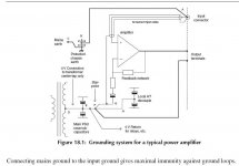
Here some "nonsense" from Douglas Self and many others obviously not so qualified audio engineers. Shure they will all learn a lot from this thread.....
Attachments
Hi , even I do not like this wiring in terms of connecting to the ground.Normal minus speaker jack is connected to the center tape secondary mains transformer not to ground plain
Alex.
best place to connect speaker minus/ground is directly on the ground wire from supply, just an inch or so from board connect
or if you use spade connector, directly from there
First things first. Please stop posting all these sources to prove your points to me. Trust me on this, I simply don't care. Those pretentious audio engineers, Ben Duncan, Douglas Self, etc. are no better than most audiophiles.
Here's a challenge for Lee Knatta, Tinitus, Jam, Krisfr, Jacco Vermeulen, and Ostripper:
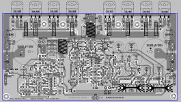
You guys are "EXPERTS" in grounding schemes and negative feedback traces, so can you please take the below picture (of Alex's current PCB layout) and draw in GREEN (Photo Shop, Paint, etc.) the correct ground traces (star ground, separate power and input ground, speaker out, transformer ground for 60VAC, etc.)? And please draw the negative feedback trace in RED. Please use the original schematic attached bellow and do not add/alter any components, or remove the ground plane.
Since the experts are at work, maybe we can finish this PCB and get to the fun part. Which is building the amp!! Posting pictures!
Here's a challenge for Lee Knatta, Tinitus, Jam, Krisfr, Jacco Vermeulen, and Ostripper:
You guys are "EXPERTS" in grounding schemes and negative feedback traces, so can you please take the below picture (of Alex's current PCB layout) and draw in GREEN (Photo Shop, Paint, etc.) the correct ground traces (star ground, separate power and input ground, speaker out, transformer ground for 60VAC, etc.)? And please draw the negative feedback trace in RED. Please use the original schematic attached bellow and do not add/alter any components, or remove the ground plane.
Since the experts are at work, maybe we can finish this PCB and get to the fun part. Which is building the amp!! Posting pictures!
Attachments

The grounding "war"
1).I suggest that Lee Knatta, Tinitus, Jam, Krisfr, Jacco Vermeulen, and Ostripper take the challenge. That will give builders two opportunities to ground this amplifier (not seven, I hope).
2).Nagys, who has offering to be the first one to populate the boards and one from the "opponents" try out both alternatives and give all others builders both listening and measurable feedback.
Until this problems are "solved" I will take a break in ordering components for building this clone
Eivind Stillingen
First things first. Please stop posting all these sources to prove your points to me. Trust me on this, I simply don't care. Those pretentious audio engineers, Ben Duncan, Douglas Self, etc. are no better than most audiophiles.
Here's a challenge for Lee Knatta, Tinitus, Jam, Krisfr, Jacco Vermeulen, and Ostripper:
You guys are "EXPERTS" in grounding schemes and negative feedback traces, so can you please take the below picture (of Alex's current PCB layout) and draw in GREEN (Photo Shop, Paint, etc.) the correct ground traces (star ground, separate power and input ground, speaker out, transformer ground for 60VAC, etc.)? And please draw the negative feedback trace in RED. Please use the original schematic attached bellow and do not add/alter any components, or remove the ground plane.
Since the experts are at work, maybe we can finish this PCB and get to the fun part. Which is building the amp!! Posting pictures!
Why should anyone want to help you with this attitude and with all the rebukes of help that have occurred so far???? You're in over your head and won't admit it.
- Home
- Amplifiers
- Solid State
- The Very Best Amplifier I Have Ever Heard!!!!