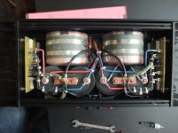
URL is dead - go toI can only speak for myself. My solution will work more than 20 years for a 600 VA transformer, infact my have worked since 1988 = 32 years. It's pretty reliable. The amp is used every day since I have it for the TV sound. More info here
Sjostrom Audio - SST01 Softstart for toroidal transformers
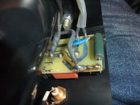
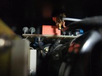
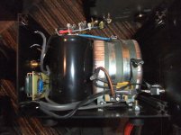
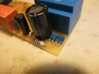
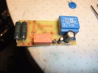
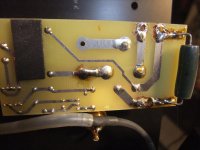
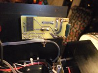
Now I have a power amp from Germans brand Horch model 3.0s on the desk with several age-related deficiencies, among other things with 3 interrupted high-load resistors connected in parallel mode on the sub board for inrush current limiter.
I want to replace the 3 pcs resistors 68R/5W by 2 pcs Caddock 50R/30W as mentioned in post #9, go to
Security Check
http://www.caddock.com/Online_catalog/Mrktg_Lit/MP9000_Series.pdf
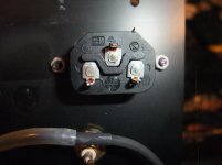
additional I want to know for replace the relais the best contact material for this application - go to
https://www.te.com/usa-en/products/...section/relay-contact-life.html?tab=pgp-story
Thank you very much for an advice.
Attachments
-
 Horch 3.0S inrush current lim-VI.jpg997.2 KB · Views: 281
 -
 Horch 3.0S inrush current lim-VIII.jpg981.6 KB · Views: 276
 -
 Horch 3.0S inrush current lim-VII.jpg1,013.4 KB · Views: 281
 -
 Horch 3.0S inrush current lim-IV.jpg900.3 KB · Views: 269
 -
 Horch 3.0S inrush current lim-III.jpg777.7 KB · Views: 267
 -
 Horch 3.0S inrush current lim-II.jpg985.4 KB · Views: 153
 -
 Horch 3.0S inrush current lim-I.jpg984.3 KB · Views: 132
 -
 Horch 3.0S inrush current lim-V.jpg1,005.8 KB · Views: 133
 -
 Horch 3.0S open top.jpg989.8 KB · Views: 161
Last edited:
typical mistake when making inrush limiter - connecting resistors in parallel
with time, even just slightly lower one in resistance is going to be stressed more and more than other ones
they need to be connected in series
use 3 NTC's , CL60 range, in series and use relay which can endure amp power consumption, simple as that
with time, even just slightly lower one in resistance is going to be stressed more and more than other ones
they need to be connected in series
use 3 NTC's , CL60 range, in series and use relay which can endure amp power consumption, simple as that
This is actually an old design, replaced 10 year ago with SST03.
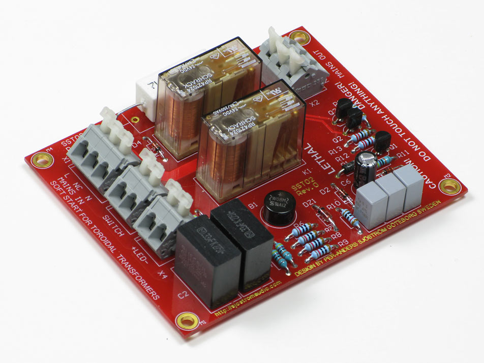
Sjostrom Audio - SST03 Softstart for toroidal transformers
ZM is right, use NTCs in series. I had one with resistors at first and if circuit fails to trip, resistors will burn up under a continuous load (and they did). NTCs on the other hand, will tend to go to low resistance when hot and can work indefinitely even if relay fails to trip.
I use a SSR so that it never wears out.
This was designed by Jhofland and I have been using this for a couple years now.
This is mine as used in SuSyLu amp:
I use a SSR so that it never wears out.
This was designed by Jhofland and I have been using this for a couple years now.
This is mine as used in SuSyLu amp:
Last edited:
the bulb gets hot not recommended sometimes it takes about 25secs to charge the large caps in secondary.
Take an example of 2KVA Transformer with 2,00,000uF for total both rails at 80VDC. Its quite a considerable amount of Inrush.
I had to use massive size NTC and it wasnt easy to control the inrush even with 40ohm for 230V.
Secondly the resistors which are used they should be able to take the thermal stress of very large value take your inrush is about 500Amps for about few seconds like may be 3 seconds at worst so you need to have 1.5KW capable resistor for instantaneous power dissipation which is usually hard.
I recommend going with NTC of larger size like which can take about 400J or 500J and you anyway need to calculate all the values accordingly.
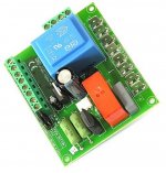
URL is dead (go to the attachment). currently URL:Hypex has it.
http://hypex.nl/docs/softstart.pdf
https://www.hypex.nl/product/softstart-module/38
Attachments
Sorry to dig up an old thread.
My transformer is 30-0-30 15 amps.
The first time I hooked it up my breaker tripped.
Also the post rectification d/c voltage was absurdly high. like 60 volts vs the 47 I was expecting. Even the a/c output voltage was quite high.
So I picked up a NTC and connected it in series with my phase line.
Right away it started working fine. Also the NTC does not get hot its room temp. At room temp its like 8 ohms.
So my question is do I leave it like this. Or should I bother with building a circuit that will bypass the NTC after a few seconds.
I also noted that my rectified d/c voltage now becomes spot on i.e. 47 volts. Even my a/c voltage output was spot on at 30 volts. And it stays there no matter how hard I drive the amp.
Long story short. What am I loosing by having 8 ohms resistor on on my a/c input. From time to time I check it and its not getting hot.
So far I cant see any reason to bypass the NTC. If I remember right its marked 8-30
Will confirm in a bit.
No way an NTC would drop the output voltage that much (from 60 to 47V). Maybe a mistake has been made during measurements (no load?). About bypassing the NTC, check its voltage drop (ACV) at high output levels. An analog voltmeter would be useful in this case. Also check PSU output DCV in that situation.
The drop depends on current draw. High current will drop quite a bit (that’s supposed to happen) but if it heats up to working temp - the resistance is about 0.5ohms and it’s minimal.Its a NTC 8D-20 9 ohms at room tep.
I will take fresh measurements. As I gave my transformer to a friend and got another one for myself. Same spec. I am not seeing any drop in use.
Is there a way to calculate loss if load is 9 ohms ?
I use three 8D-20’s in series and then use a SSR to bypass them after about 2 seconds after they have done their job of softly starting up a a toroidal trafo.

A resistive device like a varistor or resistor that is shunted out by a relay after a couple of seconds makes sense to me. In that setting, I'd prefer the resistor over the varistor. Reason is that if there is a quick succession of power outages, the resistor will always have its resistance held relatively constant, whereas the varistor needs time to cool down in order for its resistance to rise to its room temperature value and resume its provision of current limiting resistance.
I tried using 4 power resistors (4x 5W units) and the problem is a safety one. In the event that the relay fails to bypass the resistors after a few seconds, under a Class A load, the resistors will overheat and melt and burn the board. This happened to me and I had to switch to NTCs, which, although have a memory effect until they cool down, at least do not pose a fire hazard.
The legs of the resistor got so hot it melted to solder and the resistor fell off the board after burning it where it touched. It was a good thing I was there to catch it and shut it off manually as it happened during testing.
I promptly replaced the resistors with a couple of NTCs in series on a new PCB.
Assume your Class A amp draws 3A current and you have circa 30ohm resistors, power is (3A)^2 x 30ohm = 270W. You would need a resistor capable of dissipating 300w continuously. That’s a very impractical, large and expensive resistor.
Last edited:
Good idea to use 1000w halogen lamp as soft start resistor. It can indeed dissipate 300w or more continuously until bypassed. It may suffer from thermal cycling failure and eventually needs replacement as all light bulbs do. Whereas three 8D-20’s in series don’t burn out so easily. You will get a nice light show for two seconds each time it’s used - good confirmation of startup.
Lightbulbs are often used in speaker crossovers to protect tweeters.
Lightbulbs are often used in speaker crossovers to protect tweeters.
Im looking for a simple circuit to bypass the 8D-20. I found that one of them in series on the phase line works fine.The drop depends on current draw. High current will drop quite a bit (that’s supposed to happen) but if it heats up to working temp - the resistance is about 0.5ohms and it’s minimal.
I use three 8D-20’s in series and then use a SSR to bypass them after about 2 seconds after they have done their job of softly starting up a a toroidal trafo.
Im still not convinced I need to bother with bypassing it. I have checked my AMP at full volume with a 8 ohm resistor Voltage did not drop. Output did not drop. Did this test with the NTC and without it. My amps output did not change.
Most of the soft start circuits seem way to complex for the simple job they need to do which is bypass one NTC. Can you share how you wired your bypass.
Found this link helpful.
https://neurochrome.com/pages/the-ultimate-guide-to-soft-start-design
Hi Chinoy,
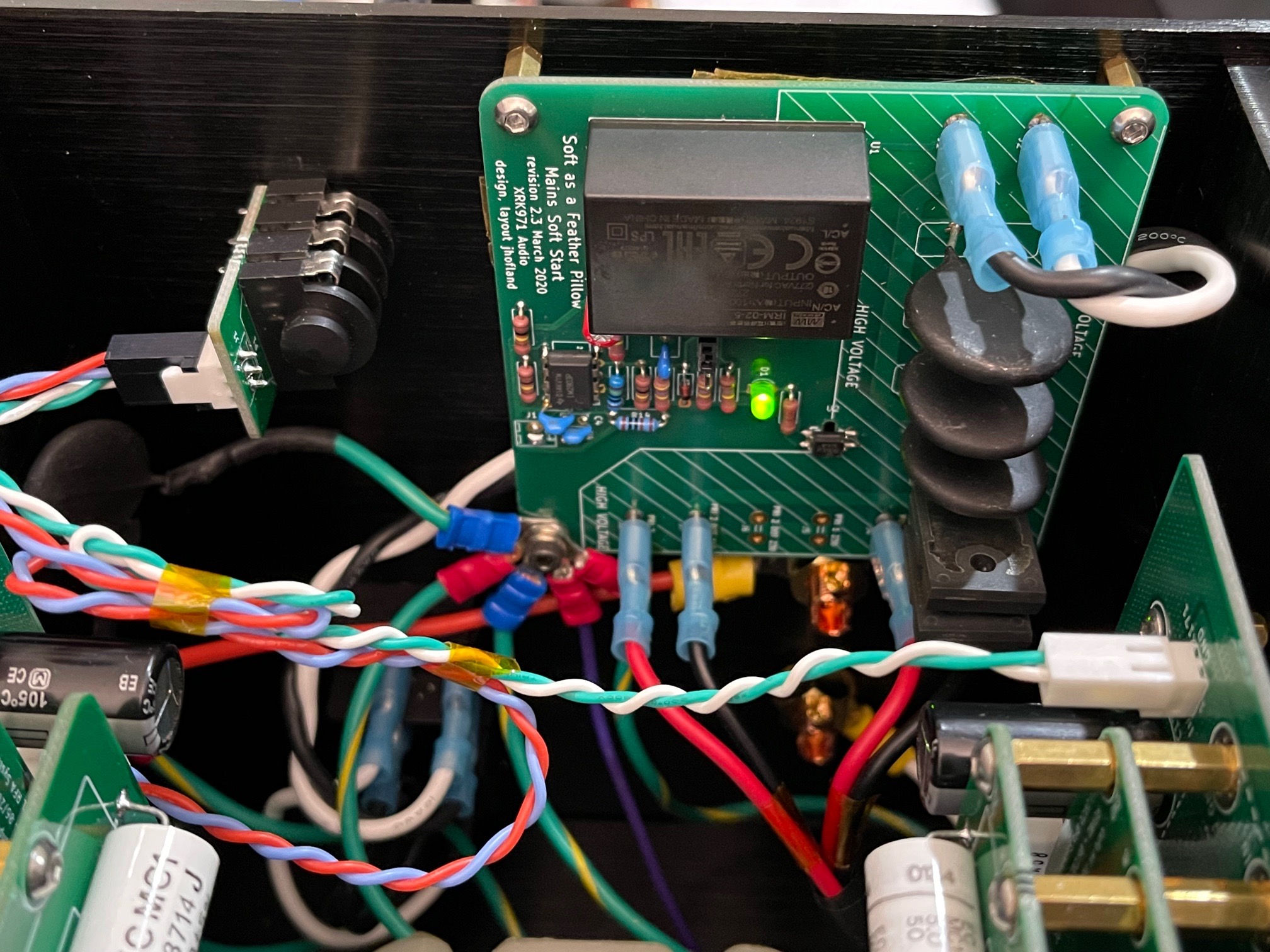
Here is the circuit I used, it was designed by Jhofland.
I suspect you may say it is too complex for such a simple job. But the job of having a relay that has essentially no on resistance and never wears out from arcing and has a reliable 2 second delay can’t be done for much less. The big bonus is that the NTCs don’t get hot for more than a second. So they can return to their high resistance state sooner and the whole thing is cool running.
But if simplicity is what you want - an always on and connected in m-series NTC like CL-60 or 8D-20 capable of handling the full current can work as a soft start - like so often used in many of the PSU’s shown on this forum (and I myself use this much of the time for development).
It has a small AC/DC that provides the always on logic controller voltage and power to effect the SSR. You have your choice of selectable delays 0.5, 1, and 2 seconds to allow the inrush to settle. Many people have used this with good success. The TLP3906 gate driver is sometimes hard to get and an easy SMT part to solder with exposed legs. U4 is optional and only needed if you want the soft start to trigger an external logic circuit or LED indicator with open collector.
Last edited:
- Home
- Amplifiers
- Pass Labs
- The ultimate Inrush Current Limiter Solution for large Toroidal Transformers