The second solution I hate, because the resistor always limit the current, if the relais contact don't longer work (transition resistance through wear and tear)
You could put a capacitor across the relay contacts to soak up any sparking of the relay contacts.
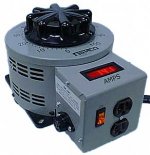
You can find some very reasonable commercial carbon rheostats that will perform the same function. You just turn your amp on manually and the toroid charges at a steady pace. Just like a variac. Mount to the faceplate and you never know it is there.
When you consider the alternative is a pcb, soldering, parts selection, auxiliary voltage source for relay and space to mount in the chassis it looks better. You also do not have that extremely hot thermistor in the system.
I have used this setup for my amps when testing and it works really good. I have not fried any bridge rectifiers since. In the past it was always the rectifiers that failed when trying to charge the huge power supplies DIY projects use. When you can continue to hear music from the speakers when the power is off for over one minute that is a major source of energy stored in the caps. And you want to charge it in one phase cycle!!!
Tad
Insush Current Limiter used Universal Motor Controller from Onsemi
What about this TDA1085C (TDA 1085, TDA 1085C) - solution from Bryston?
Good known devices and easy to realize - I think.
Who have deal with this circuit topology?
Bryston Limited - Music For A Generation
go to PowerPac P300 schematics, download PDF file and scroll down to last page
Unfortunately I don't find application notes from Motorola about
ON Semiconductor TDA1085C: Universal Motor Controller
Datasheet
http://www.onsemi.com/pub_link/Collateral/TDA1085C-D.PDF
Obviously this insrush current limiter topology idea comes from Bryston itself.
keeping smoothing capacitance low helps avoid the the need for a slow charge circuit.I have lost count of the number of threads on here where the cause of amp failure is the soft start circuit.
I try to do without one where possible. This can be done by keeping smoothing capacitors as small as is practicable.
That does not address the soft start requirement for transformers.
The fuse required to avoid nuisance blowing at start up needs to be approximately three times the maximum primary current rating of the transformer.
If one wants to close rate the mains fuse, i.e. Tfuse rating ~VA/Vac, then one must use some form of soft start circuit.
I habitually fit soft start using a timed relay bypass. I have never had a failure of the soft start circuit.
there is both to find: relay and tyristor resp. silicon controlled rectifier (or triode for alternating current resp. alternistor).Hypex has it.
http://hypex.nl/docs/softstart.pdf
Nevertheless a good advice.
Maybe the relay controls the LED in the opto isolator/opto thyristor. And the internal driver device controls the thyristor or triac.
Here a datasheet of opto isolator with integrated Triac:
http://www.fairchildsemi.com/pf/MO/MOC3063-M.html
and two additional URLs with applications for Hypex softstart
Module Hypex Softstart pour amplificateurs
http://nodecorporation.co.uk/hyp0020.htm
Attachments
Last edited:
No. This is a speed controller (and no insush current limiter) for vintage Drills & Impact Drills, e. g. from Bosch (great similarity to a AC lamp dimmer). But mostly such a device is already integrated in impact drilling tools from currently production.Hi Troyonzeiss,
do you mean something like this Power voltage controller from Brocotts on ebay
Item number 110616577592
in this case this thread is also of interest:
http://www.diyaudio.com/forums/soli...transformer-amplifier-why-what-purpose-3.html
http://www.diyaudio.com/forums/soli...transformer-amplifier-why-what-purpose-3.html
What if you just have 2 switches.
1) Mains switch which powers up transformer and capacitor supply
2) Second switch between amp and supply.
You could then just leave supply running 24 hrs a day since the current draw is virtually zero, then throw the second switch to fire up the amp when you want.
I was thinking of this just yesterday. Not sure if this is a great idea but it has some potential.
A two-switch solution I have realized some times ago in completly other kind:What if you just have 2 switches.
1) Mains switch which powers up transformer and capacitor supply
2) Second switch between amp and supply.
You could then just leave supply running 24 hrs a day since the current draw is virtually zero, then throw the second switch to fire up the amp when you want.
I was thinking of this just yesterday. Not sure if this is a great idea but it has some potential.
Two big amps (Krell model KSA-250) are in series with a halogen lamp on the power cord at mains.
First switch turns on this arrangement without any other current inrush limiter resp. soft start stuff.
Second switch short this lamp after switch on at second step. The lamp serves as current limiter resistor while switch-on the transformers of both amps.
The lamp what I mean was model CP71 - go to:
CP40 / CP71 FKJ 1000w G22 | CP lamps | MGC Lighting Group.
Very easy, but without any trouble until now.
A two-switch solution I have realized some times ago in completly other kind:
Two big amps (Krell model KSA-250) are in series with a halogen lamp on the power cord at mains.
First switch turns on this arrangement without any other current inrush limiter resp. soft start stuff.
Second switch short this lamp after switch on at second step. The lamp serves as current limiter resistor while switch-on the transformers of both amps.
The lamp what I mean was model CP71 - go to:
CP40 / CP71 FKJ 1000w G22 | CP lamps | MGC Lighting Group.
Very easy, but without any trouble until now.
Yeah. I like it
A two-switch solution I have realized some times ago in completly other kind:
Two big amps (Krell model KSA-250) are in series with a halogen lamp on the power cord at mains.
First switch turns on this arrangement without any other current inrush limiter resp. soft start stuff.
Second switch short this lamp after switch on at second step. The lamp serves as current limiter resistor while switch-on the transformers of both amps.
The lamp what I mean was model CP71 - go to:
CP40 / CP71 FKJ 1000w G22 | CP lamps | MGC Lighting Group.
Very easy, but without any trouble until now.
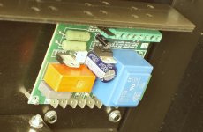
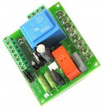
Im currently using a dual relay system where
Relay 1 turns on which can actually handle the 30A load so its like a small switch to turn on the big switch( relay1 ). Then there are 3 x 56ohm resistor in series with it and there is another relay which is in parallel with the resistors but this relay 2 will turn on after 2 seconds.
Im using it with a 1200VA Rcore trafo with 60000uf caps and it works like charm.
I resistors barely become hot ( dont touch them when you are turning on ).
But yes dual relay will even work better. I feel much better than just a NTC.
A two-switch solution I have realized some times ago in completly other kind:
Two big amps (Krell model KSA-250) are in series with a halogen lamp on the power cord at mains.
First switch turns on this arrangement without any other current inrush limiter resp. soft start stuff.
Second switch short this lamp after switch on at second step. The lamp serves as current limiter resistor while switch-on the transformers of both amps.
The lamp what I mean was model CP71 - go to:
CP40 / CP71 FKJ 1000w G22 | CP lamps | MGC Lighting Group.
Very easy, but without any trouble until now.
There is one flaw that I can think of: if the system is only constructed of the two switches (relays?) and the lamp, if the lamp burns out nothing will happen when the first relay closes, and then when the lamp is shorted there will be un-constrained turn on (no inrush suppression).
This could be made to be very fault tolerant in the following way: detect the lighting of the lamp when the first relay closes via a photodiode/photoresistor. If the lamp does not light (e.g. because it has burned out open circuit) the second relay is prevented from closing and a fault indicator is illuminated. Under that kind of fault protection I would like this arrangement very much!
I didn't think he was using relays. I was under the impression he was using regular manual/mechanical switches.There is one flaw that I can think of: if the system is only constructed of the two switches (relays?) and the lamp, if the lamp burns out nothing will happen when the first relay closes, and then when the lamp is shorted there will be un-constrained turn on (no inrush suppression).
This could be made to be very fault tolerant in the following way: detect the lighting of the lamp when the first relay closes via a photodiode/photoresistor. If the lamp does not light (e.g. because it has burned out open circuit) the second relay is prevented from closing and a fault indicator is illuminated. Under that kind of fault protection I would like this arrangement very much!
That's what I would use, I'm not a fan of relays.
Last edited:
this I have just find:
The Ultimate Guide to Soft Start Design – Neurochrome
The Ultimate Guide to Soft Start Design – Neurochrome
Maybe pre-magnetizing the core with a DC pulse and then cranking on the AC in the same direction when the source voltage is at the peak of the voltage waveform would be a way to go. By switching on at peak voltage rather at than zero crossing for inductive loads, you get a high dV/dT to which the inductance presents a high-ish impedance to limit current. I have done this successfully with large toroidal xfmrs in a workplace setting. In my case, the DC pre-charge was not even necessary.
- Home
- Amplifiers
- Pass Labs
- The ultimate Inrush Current Limiter Solution for large Toroidal Transformers