Salas.....
Originally Posted by king4joy
Salas.......For Q101, have you changed to use IRF9530 as well?? better??
What is CCS current setting and CCS-LoadCurrent??
The filament is burning at 1.25-1.50A....will there be lots of heat at Q106??
Could I use 9V-0V-9V 3.3A transformer per channel?? Or what is the smallest transformer to use to have less heat sink please??
Cheers,
King
Yes, for Q101 the original 9610 is not able to provide so much current you need without overheating. So in your case you got to use another 9530 in the CCS too.
Q106 will dissipate the difference of raw input voltage to regulated output voltage times the CCS current in W dissipation. Use a transformer that will not produce more than 7V of the above difference so you save heat. Set the CCS for 200mA more than your filament need. Q106 will have the small dissipation VS Q101 in this case because is going to burn that 200mA difference only times filament voltage in W.
Q106 will dissipate the difference of raw input voltage to regulated output voltage times the CCS current in W dissipation. Use a transformer that will not produce more than 7V of the above difference so you save heat. Set the CCS for 200mA more than your filament need. Q106 will have the small dissipation VS Q101 in this case because is going to burn that 200mA difference only times filament voltage in W.
Has anyone simulated or measured the output impedance and capacitance of the IRF9610 ccs (the one in the Reflektor schematic)?
Is it on par with cascoded constant current sources, or more in the league of non cascoded ones? It could be that this already has been covered, but I can’t find it in this mega thread.
Peter
Is it on par with cascoded constant current sources, or more in the league of non cascoded ones? It could be that this already has been covered, but I can’t find it in this mega thread.
Peter
Only in the simulator. But prediction had shown very good consistency when a member measured the output impedance at least for SSLV1.1 on an AP2 measurement station.
So the sim shows 20dB benefit at 100kHz for SSHV2's depletion cascode for instance VS single 9610. Still when talking -120dB and -140dB at 5 times the audio bandwidth I seriously doubt that the ground reference would allow that to show in any build at those frequencies. Another thing I have learned in practice is that a CCS beyond biasing the regs it is not a real firewall for really high rectification garbage no matter what its spec. The wiring loop area and traces inductance turn it to a moot point even versus just a ballast resistor. At ripple frequencies the CCS is good enough. Still with ripple comes the HF garbage so you ideally pre filter to an extent or you take common noise counter measures, so no big deal the spec against high value ripple.
So the sim shows 20dB benefit at 100kHz for SSHV2's depletion cascode for instance VS single 9610. Still when talking -120dB and -140dB at 5 times the audio bandwidth I seriously doubt that the ground reference would allow that to show in any build at those frequencies. Another thing I have learned in practice is that a CCS beyond biasing the regs it is not a real firewall for really high rectification garbage no matter what its spec. The wiring loop area and traces inductance turn it to a moot point even versus just a ballast resistor. At ripple frequencies the CCS is good enough. Still with ripple comes the HF garbage so you ideally pre filter to an extent or you take common noise counter measures, so no big deal the spec against high value ripple.
Yes, for Q101 the original 9610 is not able to provide so much current you need without overheating. So in your case you got to use another 9530 in the CCS too.
Q106 will dissipate the difference of raw input voltage to regulated output voltage times the CCS current in W dissipation. Use a transformer that will not produce more than 7V of the above difference so you save heat. Set the CCS for 200mA more than your filament need. Q106 will have the small dissipation VS Q101 in this case because is going to burn that 200mA difference only times filament voltage in W.
Salas...am I in the correct thread (the SSLV1.1 builds thread)??
If not please re-direct.
How do I set the CCS for 200mA more than the filament's need??
Is it possible to set up a T.P. and a trimmer like SSHV2??
How to calculate Ohmic and W spec for R101 please??
And for 6.0 -8.0V output, 1.5A for filament plus safty, what should I use for R303 and R305??
I have built a (quick and dirty) test board in order to try the Reflektor. The two IRF9610’s I had in my parts bin both went to heaven during testing even before I could listen to it. When it worked it was sensitive to oscillations and I think now that the current set transistor was too far away from the IRF9610 (but not more than 2cm). The funny thing is that IRF9610’s went dead without any warning. For example, I switched the circuit off, changed the value of the stop resistor, switched it on again and the IRF was gone. Are there others with similar experiences?
I am testing the Reflektor now with Gary Pimm’s BBMCCCS that was also in my parts bin. Gary Pimm's DIY audio pages
The combination works fine, but needs some extra volts to drop.
Peter
I am testing the Reflektor now with Gary Pimm’s BBMCCCS that was also in my parts bin. Gary Pimm's DIY audio pages
The combination works fine, but needs some extra volts to drop.
Peter
Salas...am I in the correct thread (the SSLV1.1 builds thread)??
If not please re-direct.
How do I set the CCS for 200mA more than the filament's need??
Is it possible to set up a T.P. and a trimmer like SSHV2??
How to calculate Ohmic and W spec for R101 please??
And for 6.0 -8.0V output, 1.5A for filament plus safty, what should I use for R303 and R305??
There is pdf guide and excel calculator in builds thread 1st post.
I go to the 1st post http://www.diyaudio.com/forums/powe...listic-salas-low-voltage-shunt-regulator.html but cannot find the calculator yet....
Please help again.
Please help again.
Salas
.
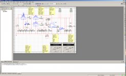
Similar schemes is used for HI-FI audio in Russia.
.
Left LM317 is used as a parametric (sequential) stabilizator with low noise, additional R5 - 0.1 Ohm, manual change C6 - 470 uF, additional C2 - 470uF, C3 - 0.47 uF .
Right LM317 is used as a current source (current generator) about ~170 mA.
OP AMP and n-MOSFET is used as a parallel stabilizator, max ~150-160 mA is stabilized.
MC7805 is a stabilized high quality voltage source with capacotors filter on out of chip.
R1 must be 6.8 Ohm - 10 Ohm, 2 Watts.
.
Similar schemes is used for HI-FI audio in Russia.
.
Left LM317 is used as a parametric (sequential) stabilizator with low noise, additional R5 - 0.1 Ohm, manual change C6 - 470 uF, additional C2 - 470uF, C3 - 0.47 uF .
Right LM317 is used as a current source (current generator) about ~170 mA.
OP AMP and n-MOSFET is used as a parallel stabilizator, max ~150-160 mA is stabilized.
MC7805 is a stabilized high quality voltage source with capacotors filter on out of chip.
R1 must be 6.8 Ohm - 10 Ohm, 2 Watts.
Last edited:
")
Salas
.
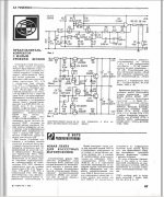
Transistors VT4, VT8 and VT5, VT10 are the current source (current generator).
Transistors VT10, VT11 are parallel (shunt) stabilizator (regulator).
VD4, VD5 are the parametric (sequential) stabilizator for VT10, VT11.
VT6, VT7 are current source (current generator) for parametric (sequential) stabilizator on VD4, VD5.
VD2, VD3 Zener 6.2V, VD4, VD5 Zener 15V .
.
Stabilized voltage +-15V, max current is about ~60-100 mA.
.
Transistors VT4, VT8 and VT5, VT10 are the current source (current generator).
Transistors VT10, VT11 are parallel (shunt) stabilizator (regulator).
VD4, VD5 are the parametric (sequential) stabilizator for VT10, VT11.
VT6, VT7 are current source (current generator) for parametric (sequential) stabilizator on VD4, VD5.
VD2, VD3 Zener 6.2V, VD4, VD5 Zener 15V .
.
Stabilized voltage +-15V, max current is about ~60-100 mA.
Last edited:
- Status
- This old topic is closed. If you want to reopen this topic, contact a moderator using the "Report Post" button.
- Home
- Amplifiers
- Power Supplies
- The simplistic Salas low voltage shunt regulator