
shunt reg for simplistic riaa
Salas,
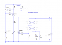
For the regulator on the attached pdf, aren;t the values for the VDC and VAC mixed up? It's not clear to me what you mean by "The input voltage of the shunt is 38 or 48 V DC, so a 28 or 36 V AC transformer is needed".
Can you please clarify what should be the input DC voltage to the regulator if I'm using the 28V (MM) operating circuit? Is it 36, 38, or 48V? Can you also confirm where I should go in with that voltage in the regulator?
I don't know what "force wire" and "sense" refer to either..
Salas,
For the regulator on the attached pdf, aren;t the values for the VDC and VAC mixed up? It's not clear to me what you mean by "The input voltage of the shunt is 38 or 48 V DC, so a 28 or 36 V AC transformer is needed".
Can you please clarify what should be the input DC voltage to the regulator if I'm using the 28V (MM) operating circuit? Is it 36, 38, or 48V? Can you also confirm where I should go in with that voltage in the regulator?
I don't know what "force wire" and "sense" refer to either..
Attachments
I have got double layer with on board rectification and filtering. Maybe you can follow some ideas from it though. If you will have your raw DC part on a different board add a decoupling capacitor across the reg's board input.
New reflektor Circuit using bipolar or Just use Bipolar Library for Mosfet? If later, it got wrong pinout. Drain M1 connect to Drain M2.
Didiet
New reflektor Circuit using bipolar or Just use Bipolar Library for Mosfet? If later, it got wrong pinout. Drain M1 connect to Drain M2.
Didiet
Bipolar library was. MOSFETS used are GDS for pins as we face them from left to right. I will look into it.
Hi all, is there a formula to calculate the heat sink size to accomodate both IRFP9240 transistors when using a version 1 circuit.
Thanks for your help
Alan
You got to calculate dissipation for each one, then the rise above ambient for total dissipation on a given sink, then add the thermal resistances case to junction and about 1W/C case to sink, looking to stay under 100C for junctions. 70-85C for junctions would be very long time safe.
The JFET is going to have about 35V across in your case. K170 has 40V max. Make R4 120R if it will be a BL range to save the JFET some dissipation. I prefer the K117 for it being less capacitive and 50V rated. But both can do, except than in the odd input over-voltage of course.

I don't know what you have in mind, but those numbers will impose certain dissipations in the Salas Style Shunt Regulator.
First, the 12V output will require a nominal 19Vdc including quite a bit of ripple.
Second, this in turn will result in a range of input voltage of 17Vdc (absolute minimum) to 19Vdc.
Third, 2A of output will likely require at least 2.03A of input.
Fourth, 19V * 2.03A gives a maximum dissipation for the whole regulator of 38.6W.
Fifth, you have to get rid of that heat using heatsinks.
I would not use a Shunt regulator for this duty, I recommend a series regulator.
Thanks for the quick reply.
Ok, i can see that there are to many compromises by using this PSU then. I am looking around for a better PSU for my DAC Magic Plus, and just gathering information and ideas. DDAC have recomended me to try his PSU Construction, and i am leaning to that sollution. But i want to keep my options open before i make my decission on what PSU to choose.
Ok, i can see that there are to many compromises by using this PSU then. I am looking around for a better PSU for my DAC Magic Plus, and just gathering information and ideas. DDAC have recomended me to try his PSU Construction, and i am leaning to that sollution. But i want to keep my options open before i make my decission on what PSU to choose.
- Status
- This old topic is closed. If you want to reopen this topic, contact a moderator using the "Report Post" button.
- Home
- Amplifiers
- Power Supplies
- The simplistic Salas low voltage shunt regulator