Salas,
The load current varies in OCXO. At power-on, it needs 500ma to warm up for approx 3 minutes. After that, it consumes 250ma constantly. Coincidently, the TC of R1 helps the load current. While R1 is hot, its resistance increases which lowers the CCS current from 630ma to 550ma. So, the temperature of IRF9610 drops a bit.
By the way, can I parallel 2 2N5458 to increase its Idss? I found several 2N5458s, but their Idss is only 4.5ma.
Last edited:
Using way too much current for those sinks I am afraid. 1R you put for R1? Theoretically you can parallel 2N5458s if they will not oscillate there. Try with the smaller Ref resistor, maybe you can narrow the drift. OCXO's PSU voltage margin? Can work between say 4.8V to 5.5V?
*Is that 0.1uF MKP necessary? Better not be there if not. At least to test if it plays a role creating instability.
*Is that 0.1uF MKP necessary? Better not be there if not. At least to test if it plays a role creating instability.
1. R1 is 4.7R as you suggest in post #3881. The circuit draws 630ma in total.
2. Well, I don't know my OCXO's voltage margin, but some manufacturers list +-5%. So, I guess 5.25V is probably the absolute maximum. It's custom made and not cheap, I really don't want to lose it.
3. In my previous PS, this 0.1uf MKP helps the sound a bit, so I decided to leave it there. I do check for oscillation, couldn't find any. Do you still think I should remove it?
If it does not oscillate, its not our right now concern. The 1.0 circuit with the Leds should draw as much with a 4R7. This one draws Vbe/R1. Would need 1R to draw around 0.6A. Something's fishy. Is the BC560 near the 9610 showing Vbe around 0.6V? If you got 2 green LEDS 2-2.2V Vf you can use them instead of the Ref resistor 27K etc. Those will resist drift. Crank the trimmer to 0 Ohm if with LEDs.
Salas,
Last night I tried to measure the vout of the 1.2R for TCXO, and it shows severe oscillation! I thought it was the oscons, so I replace them with Panasonic FM and removed the 0.1uf MKP. But, it still oscillates... I found the oscillation was due to the TCXO or OCXO. If I power my reclock circuit with the same 1.2R board, it does not oscillate. I even tried the IRF9530, but no help at all. Is there anything I should pay attention if 1.2R was fed into an XO?
Last night I tried to measure the vout of the 1.2R for TCXO, and it shows severe oscillation! I thought it was the oscons, so I replace them with Panasonic FM and removed the 0.1uf MKP. But, it still oscillates... I found the oscillation was due to the TCXO or OCXO. If I power my reclock circuit with the same 1.2R board, it does not oscillate. I even tried the IRF9530, but no help at all. Is there anything I should pay attention if 1.2R was fed into an XO?
You can attempt slowing down the reg by making the 47u output cap much bigger. If it still does not cooperate after that, there is nothing you can do more on the reg end. Maybe 1.0 can be tried. Do those clock boxes have series inductances inside or shunt ceramic capacitors along their rails?
@canvas
your shunt regulator is NOT oscillating, power supply lines are modulated by your clock") NO regulator will anything at those frequencies, your best friends there are capacitors. Small SMD capacitors, not big through-hole ones.
NO regulator will anything at those frequencies, your best friends there are capacitors. Small SMD capacitors, not big through-hole ones.
Bypass, bypass, bypass,....use different sizes & combos, multiple bypasses,... short loops, each milimeter of wire is important (1 milimeter = 0.0394").
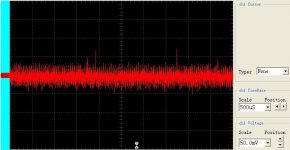
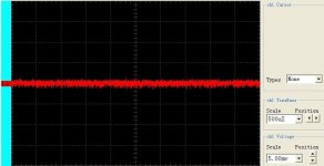
Bellow are pictures of similar situation, before and after using multiple bypasses. Put attention on voltage scale, 50m/div and 5mV/div
your shunt regulator is NOT oscillating, power supply lines are modulated by your clock
NO regulator will anything at those frequencies, your best friends there are capacitors. Small SMD capacitors, not big through-hole ones. Bypass, bypass, bypass,....use different sizes & combos, multiple bypasses,... short loops, each milimeter of wire is important (1 milimeter = 0.0394").
Bellow are pictures of similar situation, before and after using multiple bypasses. Put attention on voltage scale, 50m/div and 5mV/div
Attachments
Salas,
I replaced the 47uf with 630uf, no help. Have you ever tried the 1.2R on XOs?
Stormsonic,
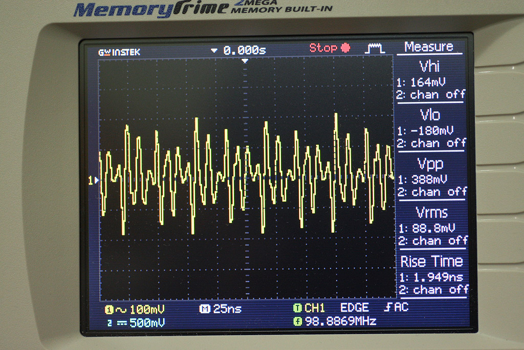
The measured freq is exactly 5 times of the TCXO. Looks like something is excited. I try to add another SMD 0.1uf ceramic directly on the vin of the TCXO, it won't do any help. Vpp is as before.
I replaced the 47uf with 630uf, no help. Have you ever tried the 1.2R on XOs?
Stormsonic,
The measured freq is exactly 5 times of the TCXO. Looks like something is excited. I try to add another SMD 0.1uf ceramic directly on the vin of the TCXO, it won't do any help. Vpp is as before.
I don't know about what can be kicking or not with such a reg and crystal oscillators, I have no experience. Enough here have used on digital circuits maybe they can give info. Being multiple frequency and so high is suspicious it has to do with the XO box non the less as Storm argued. How does the XO output look on the scope? Is it clean and useful still?
Salas,
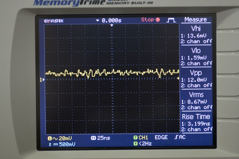
The power line is normal (flat) when XO is not connected to next stage. (#1) With clock output connected, power line was modulated (shown at post #3890), and the clock pulse has a bit of ringing. (#2)
Vout was bypassed with SMD 0.1uf, 0.01uf & 22pf, each with SMD bead connected. (like L-C-L-C-L-C) I guess 1.2R not suitable for XO?
#1
#2
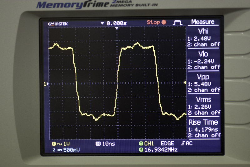
Last edited:
You managed to get Vrms modulation much lower, scale of 10. Stormsonic showed similar. I really don't know if you can have zero and with what supply. Unknown territory to me the clocks and their demands. You got to test some regs and scope for best clock and line modulation I guess. One sure thing I will not know to explain is if you tell me ''I found best scope traces with X psu but now I don't like the sound''. Wishing you best findings.
Wishing you best findings.- Status
- This old topic is closed. If you want to reopen this topic, contact a moderator using the "Report Post" button.
- Home
- Amplifiers
- Power Supplies
- The simplistic Salas low voltage shunt regulator