Vinyl is something you can hand over to your son tomorrow. It has its item appeal, its real, has pictures, you got to take care of it, makes your. Even when the true resolution files will be abundant and digital will be master quality shot through matrix with a brain fire nod interface for your pleasure, you could always spin a black weird slab to max sophistication pose in 2025.

And with that thought in mind...im off to bed...i can at least dream for the moment.
Goodnight
After a long experimentation period, combining several cap values I finally settled on the following values:
Vref - 10u
Vout - 47u EL // ((4u7u // 0.01u1837) series 0.25r metal film))
All these experiments lead me to understand that the output film cap value determines bass output.
1u is very good in tone producing very sharp bass (but if you bypass the 1u // 0.1u, you get enhancements in detail and tone becomes "light")
4u7 // 0.1u is detailed but delivers too much "evidence" in the mid high freq.
4u7 // 0.01u is quite good and my best choice.
10u is also good but I had issues due to it´s size (It was picking hum like an antena)
Hi Salas. I am setting up some Salas/Quanghao regs, and need one for 5.5 V out and ~475 mA. Should 2R be about right for R1 (and 2W)? Do I need to make any other changes (I am running fat sinks).
Thanks.
yes fit a resistor to R1 and measure.The exact current will depend on LEDS-VGS difference. There are tolerances always. Use a 5W resitor about 3R3 and see where it stands for current by dividing the voltage you will measure across, by its Ohmic value. You can trim after having that data.
Then add a second resistor to R1b to trim to your desired current.
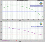
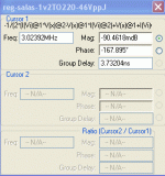
Salas - would you please post a simulation of OL gain and phase vs freq.
Best
/IR
Best
/IR
Phew, lots of drawing.
Salas - would you please post a simulation of OL gain and phase vs freq.
Best
/IR
The phase can't be right. It would oscillate it's head off on any small push when its steadier on scope and in use even more so than before.
Attachments
Efcharistå!
Hmmmm....I guess you are correct about the phase. It would oscillate if I farted in the room
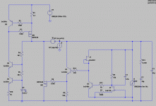
May I ask you to supply the schematic you used for the sim?
Best
/IR
Hmmmm....I guess you are correct about the phase. It would oscillate if I farted in the room

May I ask you to supply the schematic you used for the sim?
Best
/IR
The phase can't be right. It would oscillate it's head off on any small push when its steadier on scope and in use even more so than before.
Thanks...
Salas, that makes sense. In this case I would presume that some current headroom is advisable: that the CCS current should be, perhaps, 50 mA or so higher than the load current for best performance. Am I on the right track here? I realize too much current could be a problem in terms of heat.
It represents CCS current. Constant and can't be topped. Load current is just a part of the total produced by the CCS.
Salas, that makes sense. In this case I would presume that some current headroom is advisable: that the CCS current should be, perhaps, 50 mA or so higher than the load current for best performance. Am I on the right track here? I realize too much current could be a problem in terms of heat.
Efcharistå!
Hmmmm....I guess you are correct about the phase. It would oscillate if I farted in the room
May I ask you to supply the schematic you used for the sim?
Best
/IR
The 47u has 0.342R. I made and used this also beta tested it with other guys as you saw in back pages before I simulated it. So my modelling sucks.
Attachments
Salas,
nothing wrong with your simulation skills, IMO, but the real world is hard to
simulate.
I simmed your schematics in MicroCap10 using Middlebrook's method of stability check, and I got 14 degrees pahse margin and 19 dB gain margin.
See attachments.
/IR
nothing wrong with your simulation skills, IMO, but the real world is hard to
simulate.
I simmed your schematics in MicroCap10 using Middlebrook's method of stability check, and I got 14 degrees pahse margin and 19 dB gain margin.
See attachments.
/IR
The 47u has 0.342R. I made and used this also beta tested it with other guys as you saw in back pages before I simulated it. So my modelling sucks.
Attachments
That above is the R yes. The 1.2 is there: http://www.diyaudio.com/forums/powe...-voltage-shunt-regulator-190.html#post2103493
Salas,
nothing wrong with your simulation skills, IMO, but the real world is hard to
simulate.
I simmed your schematics in MicroCap10 using Middlebrook's method of stability check, and I got 14 degrees pahse margin and 19 dB gain margin.
See attachments.
/IR
Looks like that real world layout and components in the MHz for this R mousetrap need a much more sophisticated modelling to show why it works good, repeated in different builds by other members even. Best to know would be to really measure the OLG in a lab and then see what's missing from the modelling. Our results are -2deg the same. Its better I made it first and then simulated it, because I would have thought it would not work, and would have been unfortunately skipped.
Attachments
- Status
- This old topic is closed. If you want to reopen this topic, contact a moderator using the "Report Post" button.
- Home
- Amplifiers
- Power Supplies
- The simplistic Salas low voltage shunt regulator


