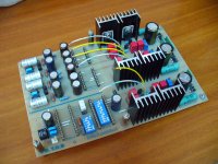
Nice one Ken. Clean, logical. Congrats. Has alternative Mosfet part numbers, yes?
Thanks Salas, yes Fairchild Mosfets. I'll post the part numbers tomorrow.
Ken
Thanks Salas, yes Fairchild Mosfets. I'll post the part numbers tomorrow.
Ken
FQA12P20 (and FQA19N20C)?
I tried to use them for my DCB1, but the CCS didn't turn on on the +ve rail.
Ken, would you kindly make some measurement the CCS Vref, V across the FET etc?
Thanks!!
FQA12P20 (and FQA19N20C)?
I tried to use them for my DCB1, but the CCS didn't turn on on the +ve rail.
Ken, would you kindly make some measurement the CCS Vref, V across the FET etc?
Thanks!!
Fred
FQA9P25.
FQA28N15
Can you mark the schematic where you would like the measurements?
@Salas
How do I calc the appropriate voltage out? Currently v-in = 32v
Ken
Hi Ken,Fred
FQA9P25.
FQA28N15
Can you mark the schematic where you would like the measurements?
@Salas
How do I calc the appropriate voltage out? Currently v-in = 32v
Ken
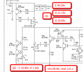
Don't have the DCB1 schematic handy. If you can measure the following 2
voltages, that will be great:
1. Voltage at CCS gate
2. Voltage across the CCS FET
Thanks!!
-fredv-
@Salas
How do I calc the appropriate voltage out? Currently v-in = 32v
Ken
You would not need drop more than 10V across the reg for it to work stably. It will work for less even, but 10 is a good number. Vout will be current through the Jfet's drain resistor times its Ohmic value +0.6V.
P.S. FQA28N15 gfs=20S typical at 16.5A! Does not have a gfs-id curve on its datasheet to see what gives in your working region, but if its analogous along the curve, its 3 times stronger than 9240. That, and Crss only 50pF its possible it drops the simulated output impedance of the reg 3 times also and is wider bandwidth as well.
To have symmetric Zo as a reg the shunt Mosfets should have the same gfs. There is capacitive difference between sexes always. Would cut on gatestopper value to create the same frequency, if there were oscillations. But I haven't used such Mosfets. You say is steady. Is it DC line on AC scope setting? Can I see a scope screen?
Salas,
for the p channel, Fairchild has a mosfet with similar gfs but higher Crss 110pf, with similar speed - FQA36P15, or one with lower gfs, lower Crss and faster - FQA9P25. Which would you pick?
Take a look into datasheet, pay attention to non-linear capacitance characteristic and Vds voltage and you will have your answer.
stormsonic,Take a look into datasheet, pay attention to non-linear capacitance characteristic and Vds voltage and you will have your answer.
this sounds like a sherlock holmes riddle...
")
Fred,
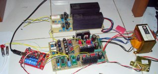
I measured a few voltages, things are pretty tight and I didn't want to short anything, so, not a lot of measurements. If there are some specific spots, tell me which one and I will give it a second try.
Ken
Hi Ken,
You numbers confirmed what I suspected. I think I have enough to play with.
Thanks a lot!!
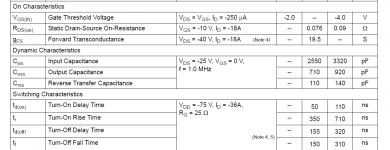
AndrewT, according to datasheet, Vgs treshold is 3 - 5V, a little bit higher than IRFP's (2 - 4V). And graph is showing 4.8V Vgs@200mA @ 25°C.
FWIW, I measured 30 FQA12P20C last Sunday, all had Vgs in the 5.0X range at 200ma. I also measured 50 IRFP9240, they were in 3.9X - 4.0X range.
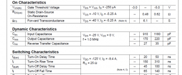
I know the schematic says FQP12P20, but, I used a FQA9p25... data sheet for the device shows Vgs of 5.75 at 200ma. If I'm reading the data sheet for the FQA9P25 correctly, the Id at 9 volts of Vds is only 100ma compared to 3A for the 9240.
Given the variables of different Mosfets, is there a way to measure the impedance of the shunt?
Given the variables of different Mosfets, is there a way to measure the impedance of the shunt?

Given the variables of different Mosfets, is there a way to measure the impedance of the shunt?
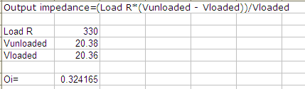
In general: Output impedance=(Load R*(Vunloaded - Vloaded))/Vloaded
Now to be equipped for measuring in the mOhm....
- Status
- This old topic is closed. If you want to reopen this topic, contact a moderator using the "Report Post" button.
- Home
- Amplifiers
- Power Supplies
- The simplistic Salas low voltage shunt regulator