I think this is also Rush cascode. Very nice sounding amp btw.
DLH Amplifier: The trilogy with PLH and JLH amps
DLH Amplifier: The trilogy with PLH and JLH amps
There's also this. In 2010 I discovered the Rush pair with offset helper transistors could be used to generate a surprisingly pure and adjustable 2nd harmonic:
Rush Cascode Headphone Amp + JLH Output Stage
Rush Cascode Headphone Amp + JLH Output Stage
Which is the common base transistor necessary to get a cascode ?I think this is also Rush cascode. Very nice sounding amp btw.
T4 is common base but used as a constant current source.
Last edited:
So my question is : why should the insertion of the buffer between the feedback network and the emitter of the input transistor should change the mode of this transistor from common emitter to common base ?
When the emitter-coupled pair is used to subtract the feedback voltage from the input voltage in an amplifier, then the transistors in the emitter-coupled pair operate differently: the input transistor of the pair operates in common-emitter mode, while the transistor to which the negative feedback network is connected operates as an emitter follower, buffering the negative feedback network from the emitter of the input common-emitter stage.
I think that there is some agreement that the common electrode configuration is not clearly defined in some circumstances, particularly for a transistor at the input of a feedback amplifying circuit.When the emitter-coupled pair is used to subtract the feedback voltage from the input voltage in an amplifier, then the transistors in the emitter-coupled pair operate differently: the input transistor of the pair operates in common-emitter mode, while the transistor to which the negative feedback network is connected operates as an emitter follower, buffering the negative feedback network from the emitter of the input common-emitter stage.
These "common status" emanate from models of configurations for humans.
When things seem difficult to grasp, it's better to forget them for a while and look at what happens on each of its electrodes instead to try to define which one is in common mode.
A transistor does not "know" what is the concept of common configuration modes. It obeys to electronic rules, the mains ones of which are really simple.
For a NPN, the difference of voltages between its base and its emitter controls, according to a value named transconductance, the current flows from its collector to its emitter.
In a non-inverting amplifier having a single transistor input stage, the input voltage is applied to its base and the feedback voltage to its emitter.
So each of the electrodes received a signal in the form of a difference of potential.
The two receiving points, emitter and base, constitute a differential input.
[*]
None of the two can be considered as being a common electrode.
Buffering the feedback by an emitter follower, either in parallel (long tail pair) or in series (Rush circuit) does not not change this fact.
Keantoken post #14 said:[*]...consider that even a single transistor could be considered a differential, as in a singleton amplifier topology...
I would like to attract your attention about a phenomena that occurs with Rush cascode.
Every one knows the transistors cause dynamic compression, how about putting one on the feedback, than it will cause dynamic expansion.
If consider in voltage character, the feedbacking transistor is just an emitter follower to lower the feedback impedance, hence, increase the error gain but bringing an extra active pole. If you consider now in current character the two transistors act as analog XOR.
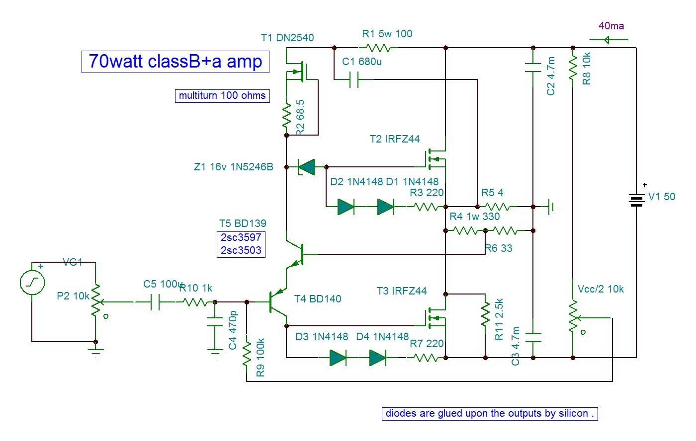
This is my circuit I used for trials.
With BD transistors which have very low Re, It has enhanced dynamic sound. I replaced the feedbacking one with a mosfet IRFBC20, I got the sound with enhanced high frequencies as if the treble control is set to 3 o'clock, although the frequency response measured flat. To try out higher gm mosfet but being low voltage, I mounted it in cascode with a common base. This time I got it even much higher enhanced high frequencies revealing in the music sounds I never heard before, always with flat response.
I replaced the input transistor also with a mosfet, all the magic disappeared, but puting it in compound Darlington with bc337, I still have the high frequencies dynamical expansion but only at very high frequencies as if I used a graphic equalizer with 16k max and the 8k +6db. As I left home a year ago, the experience remained unfinished.
Every one knows the transistors cause dynamic compression, how about putting one on the feedback, than it will cause dynamic expansion.
If consider in voltage character, the feedbacking transistor is just an emitter follower to lower the feedback impedance, hence, increase the error gain but bringing an extra active pole. If you consider now in current character the two transistors act as analog XOR.
This is my circuit I used for trials.
With BD transistors which have very low Re, It has enhanced dynamic sound. I replaced the feedbacking one with a mosfet IRFBC20, I got the sound with enhanced high frequencies as if the treble control is set to 3 o'clock, although the frequency response measured flat. To try out higher gm mosfet but being low voltage, I mounted it in cascode with a common base. This time I got it even much higher enhanced high frequencies revealing in the music sounds I never heard before, always with flat response.
I replaced the input transistor also with a mosfet, all the magic disappeared, but puting it in compound Darlington with bc337, I still have the high frequencies dynamical expansion but only at very high frequencies as if I used a graphic equalizer with 16k max and the 8k +6db. As I left home a year ago, the experience remained unfinished.
Last edited:
What do you think of a case where a new and inappropriate terminology has been invented for an old and very well known topology, and then, the following undertandings went wrong ?When the misunderstandings are corrected, the terminology tends to follow anyway. Correct terminology can follow from correct understanding, but terminology in itself likely can't correct a misunderstanding.
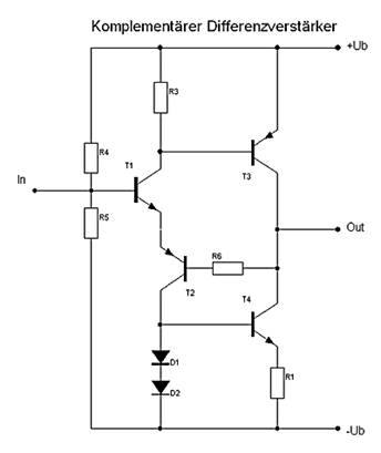
Everything was invented before us  The circuit contains two! Cascades with emitter coupling.
Direct-coupled complementary transistor amplifier (1956)
US2885498A - Direct-coupled complementary transistor amplifier
- Google Patents
The circuit contains two! Cascades with emitter coupling.Direct-coupled complementary transistor amplifier (1956)
US2885498A - Direct-coupled complementary transistor amplifier
- Google Patents

I found this gem on page 591:
The term compensation is applied to modifying an amplifier to improve it's dynamic response. It might be argued that an amplifier should be "designed" from the outset to have the optimum response, so that no "compensation" is required. However, design is essentially a trial-and-error process of weighing one improvement against another, and compensation (in the sense of choosing the best compromise) is thus and integral part. Compensation (in the sense of experimental fiddling with an amplifier after it has been constructed) is a thoroughly reprehensible practice.
- Home
- Amplifiers
- Solid State
- The Rush Cascode: Possible Wiki page