Gotcha. I've the opposite scenario. I've some 6l6gc's and a smattering of small triode's and some ...improvised output transformers and power transformers, and figured the RLD wasn't a bad place to start if I were to whack something together for fun.
I might just do a wee bit more research anyway and see how I can make a led bias string work for me.
Thanks for the reply 6L6. I had a bit of a laugh when I searched that string in the thread.")
I might just do a wee bit more research anyway and see how I can make a led bias string work for me.
Thanks for the reply 6L6. I had a bit of a laugh when I searched that string in the thread.
Yeah, I'm definitely not talking about a glorious quality build here... More a cobbling together of parts and getting it to make some noise for the sake of learning
Ok if the basic idea is sound, I better go learn about applying loadlines and bias to those output tubes. Best I read the article again!
Cheers for the confirmation that it can be done!
Ok if the basic idea is sound, I better go learn about applying loadlines and bias to those output tubes. Best I read the article again!
Cheers for the confirmation that it can be done!
Do I have this (roughly) correct? The cathodes on the 6L6's need to be at ~34V or so (I pulled that's number from a datasheet)? Meaning a string of 19 red LEDs or so... With more in strings in parallel due to higher bias current. I'd best check how many cheapie old red LEDs I have if I'm to be using that many! Add a sanity check, does that sound about right?
SY used an IR LED in one of his other projects -- i did some initial testing, and indeed they were lower dynamic impedance than the HLMP devices I had on hand. Unfortunately, unless you have a FLIR camera you can't see 'em glow.
a 10W red LED matrix with Vf of 5.2V also had low impedance, but you'll have to do a good job of removing heat.
a 10W red LED matrix with Vf of 5.2V also had low impedance, but you'll have to do a good job of removing heat.
I experimented with LED arrays in any possible combination (SHIII project) for output stage on comparable AD10 tubes and a couple of others. Not any close to a Hi-Fi, they sounds very mediocre with that harsh tone added.
The BEST result I got was with those 200-500mA white LEDs they put in the flat backlit LCD monitors. Just find one for $10 on a craigslist, or the non-working one of the most latest model would fit the best on cost/benefit. The monitor LEDs are designed to survive for long with stable parameters, and that's what we want for particularly this purpose.
But the old good R+C easily beats it on sound quality. Or, you can get better results with CCS or Zener, depends on implementation.
I find the red (1x, 2x, or 3x) LED bias sounding good in first stages though.
I experimented with LED arrays in any possible combination (SHIII project) for output stage on comparable AD10 tubes and a couple of others. Not any close to a Hi-Fi, they sounds very mediocre with that harsh tone added.
Reading that thread "SHIII project, All-Pentode PP", the problem doesn't seem to derive from the LED matrix.
Instructive to read the entire article in DIYMAG.
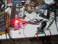
Oh, I started with use of LED arrays in output stage cathodes as you see on the photo, evaluated the LEDs again after fixing the first stage into pentode mode, but after hours of auditioning got back to a simple R+C+Z bias. I also tried to use a smaller array instead of Zener (a double line of LEDs with equivalent Vz) with R+C, but my ear voted against it.
That project had been put aside, I will get back to it in near future and post the latest schematics.
That project had been put aside, I will get back to it in near future and post the latest schematics.
each leg of the LED string should run @10mA or a bit higher to assure that they are operating linearly -- parallel LED strings need balancing resistors -- perhaps you had one string hogging current and another starved such that one was running in the exponential rather than linear portion of the Vf/I curve.
if i recall correctly, the SHIII project was running single ended. RLD is differential. using one LED array for two tubes cancels common mode small signal non-linearities per SY's article.
i'm circling back to this old thread, haven't built RLD yet, just testing before committing copper to solder! not trying to lob a brick in anyone's direction.
I had 6 strings actually, combined out of few 20-element DC-20/20SRWA red arrays and networked similarly to RLD with a small R in each.
The reason of using 20-element arrays was a better chance to get them with identical characteristics, rather than matching the discrete ones.
The quiescence current of that "common CCS" was 70 mA for the output stage pair, with each loaded to a SE OPT. Which makes it about 12 mA per a string. Did not like the sound.
Then I separated cathodes by 3 strings per tube, but neither liked it this way.
Then I replaced 2 x SE trafos with a PP one and tested both ways again, sounded a little better, but you really have to have a matched pair of tubes to get any acceptable sounding amp out of this. If you get that matched pair working good enough you may later face the impossibility to replace it with a new one, the LED array implementation is very sensitive to this. Another pair with a Vc just e.g. 0.5V higher will take the it far out from the optimal operating point - this is a quite big disadvantage I discovered about RLD.
Basically, the whole array works like a single powerful Zener.
Then, with trying to relax that sensitivity I bypassed array with a resistor (with also adding 1-2 LEDs to each string) and this sounded much better, but. .. the LEDs would flash only on signal's peaks.
Then, with right timing one of monitors died in the office, and I experimented with white ones, could not find their exact specs but seemed 200 mA ones, and kind of liked these best. They handled the peaks sonically better than the common LEDs. So, IMO, a double string of 50 mA ones would also be better choice.
But after all returned back to RCZ. This is my humble experience.
Sure, try it out, let us know of your findings.
Last edited:
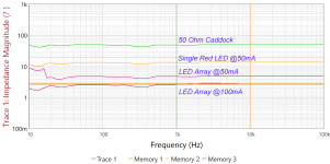
Turns out that at 10mA the dynamic impedance of the single-chip array is 9.2 ohms with Vf of 5.2V -- as you need two it isn't quite satisfactory. If, however, the array is bypassed with 100uF the impedance is ~1.6 ohm.
I would expect the array to have lower Z around 80mA, so will test tomorrow with 6BQ5 at this quiescent current.
I would expect the array to have lower Z around 80mA, so will test tomorrow with 6BQ5 at this quiescent current.
The arrays are these from Marlin Jones, Vf is 5.5V so you'll need two for each channel:
350 Lumen 10 Watt Super Bright, Red LED | MPJA.COM
Just using the setup suggested by SY in the DIYMAG article, plate load resistor is 220R/3W. Adjust the plate voltage until you reach 80mA.
Some measurements -- this is one array -- the dynamic impedance @1kHz and 100mA is 2.7 ohms, so two arrays will get you in the 11V ballpark at 5.4 ohms. The single red led should read 10mA, not 50mA
Attachments

So, I had an idea, probably not a good one, but just a thought. This will only work with some tubes, if it will work at all. We all(lots of us) seem to want an UL RLD but the screen is tied up being a screen grid. Well, on an EL34 the suppressor grid, g3, is busy suppressing and comes out to a separate pin, unlike on most tubes were it is internally tied to the cathode. Suppose we put an independent negative voltage on it and use it to balance the anode current? I know, crazy idea, but will it work? Make it a very high impedance so it can't pull much current if it ever goes positive.
I've tried to build an ultralinear PP amp with EL86, but ran into issues with the limit of screen voltage. The plate was 225, and with ultralinear the tube was red-plating.
I'd like to regulate the screens, and the RLD topology appears to be ideal for tubes that have limitations on screen voltages.
Has anyone built an EL86 version?
I'd like to regulate the screens, and the RLD topology appears to be ideal for tubes that have limitations on screen voltages.
Has anyone built an EL86 version?
- Home
- Amplifiers
- Tubes / Valves
- The Red Light District - another PP EL84 amp