I read SYs excellent RLD amp article on the SYclotron page several years ago, really more interested in the regulated screen grid ideas than the LED cathode bias. It was early in my journey and I suppose I just didn't "get" the benefits of a low cathode impedance. I'm fooling around with an EL84 project now, and want to build it as a RLD, so I went down to the local junk shop and picked up some LED samples.
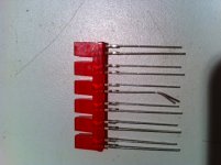
So check out this 6 pack of LEDs! Perfect, no! They have RLD written all over them. So imagine my utter disappointment when I measured dynamic impedance at 13.7R per each.
I did pick up a NOS pair of 829Bs for crazy cheap so I will stop complaining forthwith. And I did find some LEDs that measured 5R.
-CD
Attachments
SY may have a different view but I would not get too hung up on the higher dynamic impedance LEDS. In fact they may actually work to your benefit. There is some opinion that a small common impedance in the cathode circuit (typically up to around 40 Ohms for EL84 pair) helps reduce odd harmonic distortions and intermodulation distortion by introducing some common mode feedback. I use a common 39 Ohms in my PP EL84 Amp but unlike the RLD it is fixed biased and Ultralinear. I don't have the gear to quantitatively prove this, but my ears suggest that it is right.
Cheers,
Ian
Cheers,
Ian
Ian,
That's interesting.
And there is another factor I didn't mention. These LEDs run from 2.1 to 2.2 VDC per each. I'd only need five to get 11 VDC which is something of a mitigating factor. I'd like to keep the trimmer pot which can eat up about a half volt so I could live with the result.
I might still use these. It appeals to my laziness (Although I grant you these things are difficult to measure, I'd wager I'm easliy half-again as lazy as SY has claimed to be)
And too, the package was born for this use and would be both a space and time saver, not to mention neatness points.
-CD
If its any help Capt Dave, I have an amp with 6V6 outputs that was originally using LED arrays (inspired by the RLD) with individual screen grid regulators using the LR8N IC. Later on I disconnected the LED arrays and ran a fixed bias, the grid 1 voltage bias was the same for each output tube pair, and the idle current for each tube adjusted with the individual screen regs. I also used Gingertubes' mosfet source followers from the Baby Huey amp, which have to be tried to be believed. The amp sounds very nice to me. Regarding screen grid regs - short answer is it seems to work well. I regulated the screens on a tube guitar amp recently to 75% of the B+, that seemed to improve an amp that already sounded good. All interesting stuff.
Ian,
So many ideas, so little time. Interesting bias method, do you use a separate regulator for each pentode? I've been planning to build Gingertubes source followers for some time. I have a cigar box full of Mouser bags on the shelf. I'm working on screen regulators now using Heath Workman's boards. Perhaps this weekend. Thanks for the ideas.
Brisbane? Are you familiar with The Grates?
-CD
Last edited:
Never heard of the Grates before, they sound interesting.
Really, you can't go wrong listening to SY or Gingertubes, I'm just a tinkerer. Their designs are really good. Yes I used a seperate reg for each pentode but that was mainly because the LR8N has limited current capability. Sy's regulator would probably be much better, but as I said, I like to tinker/experiment. I am very grateful that these two, and a few others on this forum, freely share their profound knowledge. I built a couple of nice amps, and stopped building any more because I was happy with them. Not sure if that is a good or bad thing")
Really, you can't go wrong listening to SY or Gingertubes, I'm just a tinkerer. Their designs are really good. Yes I used a seperate reg for each pentode but that was mainly because the LR8N has limited current capability. Sy's regulator would probably be much better, but as I said, I like to tinker/experiment. I am very grateful that these two, and a few others on this forum, freely share their profound knowledge. I built a couple of nice amps, and stopped building any more because I was happy with them. Not sure if that is a good or bad thing
Last edited:
Yes I used a seperate reg for each pentode but that was mainly because the LR8N has limited current capability.
You can increase the current carrying capability of the LR8N with a pass transistor. I have it on my "to do" list to examine the PSRR and Zout with and without.
It really is a neat little device.
Ian444,
The Grates are an indi rock band from your town that I meet at a SXSW (music festival in Austin) day show a few years ago. They were terrific and I thought they would make a big splash. Catch them if you can.
I share your admiration and gratitude. I had an interest in the hobby back in the late sixties but stalled out for lack of a knowledgable mentor in my small community. I find it transformative to find virtual mentorship in this global community.
LED board blowing out
hi guys.
i finally got around to starting my RLD the other day. and am having problems with the LED boards going out in the right channel. actually a loud snap n flash across the board so is more like blowing out! not just going out. some info n pics on the build can be found here. Hawthorne Audio • View topic - red light district build?
i love the Hawthorne forum n thought id share my experiences here too.
"it seemed to start up just fine. had the new amp smell. about a minute in maybe 90 sec, a loud snap and an LED board went out. no smoke, nothing came apart. no visual evidence of the failure. upon inspection of the board i found that the 1ohm resistor seems to be completly shot. looks fine but no conductivity n i tried like hell. its like it blew like a fuse but looks fine. now im nervous to try it again. not sure what caused it."
well i end up building a new LED board n put it in. fearing the worst i turned it back on expecting the same thing. started normally again and made it 2-3 mins before the snap n flash across the right ch board again. during that time i was trying to measure the volatge across the 1R0 resistor on the opposite board. started fiddling with the meter probs to get a reading n wasted my precious time measuring the left side that didnt blow out. it was about 50v. n then lost the right board again w/o getting a measurement! dang!
any ideas whats causing this? i gotta wait now to get more leds, or maybe R shack might have some high dollar crap i could try n use just for the sake of figuring it out. it might be worth noting that after the first failure i switched to using one screen supply regulator cuz initially i didnt know exactlly where that snap came from.
any advice on any part of the build is welcome. on pg 5 of the build thread i have a really crude drawing of my power supply that might be good for some laughs hehe
peace
phil
wish id have gotten that measurement
hi guys.
i finally got around to starting my RLD the other day. and am having problems with the LED boards going out in the right channel. actually a loud snap n flash across the board so is more like blowing out! not just going out. some info n pics on the build can be found here. Hawthorne Audio • View topic - red light district build?
i love the Hawthorne forum n thought id share my experiences here too.
"it seemed to start up just fine. had the new amp smell. about a minute in maybe 90 sec, a loud snap and an LED board went out. no smoke, nothing came apart. no visual evidence of the failure. upon inspection of the board i found that the 1ohm resistor seems to be completly shot. looks fine but no conductivity n i tried like hell. its like it blew like a fuse but looks fine. now im nervous to try it again. not sure what caused it."
well i end up building a new LED board n put it in. fearing the worst i turned it back on expecting the same thing. started normally again and made it 2-3 mins before the snap n flash across the right ch board again. during that time i was trying to measure the volatge across the 1R0 resistor on the opposite board. started fiddling with the meter probs to get a reading n wasted my precious time measuring the left side that didnt blow out. it was about 50v. n then lost the right board again w/o getting a measurement!
dang! any ideas whats causing this? i gotta wait now to get more leds, or maybe R shack might have some high dollar crap i could try n use just for the sake of figuring it out. it might be worth noting that after the first failure i switched to using one screen supply regulator cuz initially i didnt know exactlly where that snap came from.
any advice on any part of the build is welcome. on pg 5 of the build thread i have a really crude drawing of my power supply that might be good for some laughs
hehepeace
phil
wish id have gotten that measurement
50v or 50mv?
I'd suggest re-reading the last page of SYs article at syclotron.com. He has a good startup procedure. The one thing I'd do differently is to bring up the amp on a Variac. That will buy you as much time as you need troubleshoot the problem. Obviously, you have too much current through the cathode circuit. My guess is that you either have 1) a wiring error such as miswiring the tube socket (ie screen grid voltage on the array?) or 2) the regulated screen supply is at max voltage rather than minimum.
You can more easily check these wild guesses with the tube removed from the socket. I'd run the screen supply up and down with the DVM attached to G2 and see that it's working correctly.
Another thing. I tested some LEDs to failure and found that they could tolerate 45ma for a long period. They failed only after current exceeded 50ma. And, they failed shorted, not open. Two things can be concluded, first your current must be in excess of 350ma if your LEDs are as robust as the ones I tested. I wonder whether a pair of EL84s could fart that much current under any circumstances; I'm betting on a wiring error. Second, since they tend to fail closed, it appears that your resistor popped like a fuse as it suddenly saw a 11v voltage spike.
Good luck, tell us how it turns out.
Good luck, tell us how it turns out.
Phil, until you get the wiring error sorted out, sub a 270R 5W resistor for the LED array- it will save you a lot of money and hassle!
You may have also lost some power tubes in the debacle, so try to use a fresh set- if the old ones survived, you've now got spares. One easy error to make is getting the feedback the wrong way around, whereupon the amp turns into a power oscillator, then self-destructs. It won't hurt to put a shorting plug at the input, then disconnect the feedback for basic DC checks.
You may have also lost some power tubes in the debacle, so try to use a fresh set- if the old ones survived, you've now got spares. One easy error to make is getting the feedback the wrong way around, whereupon the amp turns into a power oscillator, then self-destructs. It won't hurt to put a shorting plug at the input, then disconnect the feedback for basic DC checks.
Entirely possible- that would certainly cause flashes, sparks, and smoking! Definitely replace the output tubes on that side- if you burned out the small cathode resistor, replace it as well (it's a cheap part which can help protect the more expensive ones). It may have saved your LEDs and tubes, but don't count on it...
- Home
- Amplifiers
- Tubes / Valves
- The Red Light District - another PP EL84 amp