Fix for rev 35f phonoclone boards.
I will be emailing all those affected. Give me 24h to coordinate a coherent response.
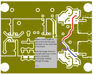
Meanwhile, the basic procedure to fix the rev 35f boards is shown in the image attached. All you need to do is bridge over the broken trace with a short length of wire. The convenient connection points are the component leads of R11 and C7 which stick out slightly from the bottom of the board.
I will be emailing all those affected. Give me 24h to coordinate a coherent response.
Meanwhile, the basic procedure to fix the rev 35f boards is shown in the image attached. All you need to do is bridge over the broken trace with a short length of wire. The convenient connection points are the component leads of R11 and C7 which stick out slightly from the bottom of the board.
Attachments
Last edited:
SERVICE NOTICE
There is an error in revision 35f of the Phonoclone 3 printed circuit boards. As a result the negative regulated voltage (V-) that feeds the phonoclone circuit (IC1, IC2) will not power up. DO NOT CONNECT YOUR CARTRIDGE TO THE PHONOCLONE UNTIL THIS ISSUE IS FIXED! The high input offset voltage could damage your cartridge.
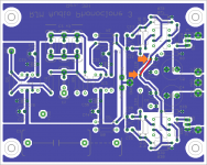
The cause of the problem is known. A 0.1” section of trace on the bottom copper layer was accidentally deleted during the editing process of the rev. 35f boards. This breaks the connection to R11 from the power supply, so the negative side of the X-reg loses its reference voltage and the output drops to near zero.
The error is only present on the rev. 35f boards.
I will provide new, updated boards as replacements for the rev 35f boards that were shipped. It will take about 1 month until they will be delivered. People who have not started working their phonoclones are encouraged to wait for the new boards. Those of you who have already started soldering can simply bridge over the pads.
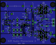
This attached image is a view of the Phonoclone 3 board looking at it flipped over, showing the bottom trace. The missing section of trace is just a tiny sliver above the bottom pad of R11, at the lower orange arrow.
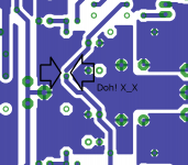
To get the boards working, a wire (shown as the red line) must be soldered between the two pads indicated by the orange arrows. If I was building the boards from scratch, I would just bend the lead of R11 over to the lead of C7 and solder the two together. If I had already completed the boards and trimmed the leads, a spare section of resistor lead bent to the right shape to go across the two pads would serve just as well.
There is an error in revision 35f of the Phonoclone 3 printed circuit boards. As a result the negative regulated voltage (V-) that feeds the phonoclone circuit (IC1, IC2) will not power up. DO NOT CONNECT YOUR CARTRIDGE TO THE PHONOCLONE UNTIL THIS ISSUE IS FIXED! The high input offset voltage could damage your cartridge.
The cause of the problem is known. A 0.1” section of trace on the bottom copper layer was accidentally deleted during the editing process of the rev. 35f boards. This breaks the connection to R11 from the power supply, so the negative side of the X-reg loses its reference voltage and the output drops to near zero.
The error is only present on the rev. 35f boards.
I will provide new, updated boards as replacements for the rev 35f boards that were shipped. It will take about 1 month until they will be delivered. People who have not started working their phonoclones are encouraged to wait for the new boards. Those of you who have already started soldering can simply bridge over the pads.
This attached image is a view of the Phonoclone 3 board looking at it flipped over, showing the bottom trace. The missing section of trace is just a tiny sliver above the bottom pad of R11, at the lower orange arrow.
To get the boards working, a wire (shown as the red line) must be soldered between the two pads indicated by the orange arrows. If I was building the boards from scratch, I would just bend the lead of R11 over to the lead of C7 and solder the two together. If I had already completed the boards and trimmed the leads, a spare section of resistor lead bent to the right shape to go across the two pads would serve just as well.
Attachments
Last edited:
The ARC PH3 is a fine-sounding phono stage. Stiff competition. Even with the Phonoclone at 100% I would expect a shoot-out to be indecisive at best.
Regarding RFI, some people do have problems. Using well-shielded phono cables, cases and interconnects is an absolute must. The power umbilical can be unshielded though in severe environments it too may benefit from shielding.
After two days of listening, it seems that indeed things are getting better. I like what I hear
") Seems a very promising device.
Seems a very promising device.About shielding umbical and power cables, I usually think of the issue from the side that they are creating interference and not so much receiving it. Especially the 230V AC cable. So I usually use some nice quality shielded cable like olflex 110 cy terminating its shieling only on the earth of the wall plug. And it s not that more expensive than pure computer grade IEC cable (~1 euros /foot). Plugs of course is another issue (not gonna open that door here
)Further to my construction, I have disassebled everything and I am re-drilling the test chassis so that I have a better and more functional layout. I m sacrificing a bit of looks (seamless/screwless/smooth case with everything mounted on the bottom) but I guess sonics > looks.... or... hmmmm
I also probably need to shorten my interconnect (currently ~3 feet of shielded cardas litz wire)
By the way, what is the output impedance on phonoclone and vpsp?
47 ohm.
Phonoclone 35h
Gradually climbing out of the hole I dug for myself.
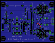
Phonoclone 3 boards rev. 35h, which fix the trace issue found on 35f, has been drawn up, finalized, and sent for fabrication. Turnaround is about 2 weeks back to me, another week or so to get out to those who need them.
Gradually climbing out of the hole I dug for myself.
Phonoclone 3 boards rev. 35h, which fix the trace issue found on 35f, has been drawn up, finalized, and sent for fabrication. Turnaround is about 2 weeks back to me, another week or so to get out to those who need them.
Attachments
Something is amiss
I finished my Phonoclone 3 boards this morning (rev 35c). The power
supply checks out. The voltage at IN+ and IN- and OUT+ and OUT- are 0
V. V++ and V-- are 35 V. IC socket 1, however reads +.6 and -.6 V.
The only thing that was not by the book was I used at 2610 ohm
resistors at R2 when your Phonoclone calculator calculated 2500
because I had them on hand.
The cartridge is the MC that comes with the Clearaudio Concept turntable:
MC Cartridge / Pick-up:
Output Voltage (1kHz, 5cm/s): 0.4 mV at 5 cm/s
Channel Separation (1kHz): > 30 dB
Channel Balance (1kHz): < 0.5 dB
Tracking Ability: 80 μm
Tracking Force: 2.0 gram (+/- 0.2 gram)
Load Resistance: 100 Ohm
Load Capacitance: 100 pF
I used 100 and 0.4 in the calculator and it read 100 ohm for R1 and 2500 for R2.
I went ahead an put in the ICs and hooked it up. No sound came out
when hooked up to the turntable and amp.
Here is a pic
Any ideas?
Thanks.
I finished my Phonoclone 3 boards this morning (rev 35c). The power
supply checks out. The voltage at IN+ and IN- and OUT+ and OUT- are 0
V. V++ and V-- are 35 V. IC socket 1, however reads +.6 and -.6 V.
The only thing that was not by the book was I used at 2610 ohm
resistors at R2 when your Phonoclone calculator calculated 2500
because I had them on hand.
The cartridge is the MC that comes with the Clearaudio Concept turntable:
MC Cartridge / Pick-up:
Output Voltage (1kHz, 5cm/s): 0.4 mV at 5 cm/s
Channel Separation (1kHz): > 30 dB
Channel Balance (1kHz): < 0.5 dB
Tracking Ability: 80 μm
Tracking Force: 2.0 gram (+/- 0.2 gram)
Load Resistance: 100 Ohm
Load Capacitance: 100 pF
I used 100 and 0.4 in the calculator and it read 100 ohm for R1 and 2500 for R2.
I went ahead an put in the ICs and hooked it up. No sound came out
when hooked up to the turntable and amp.
Here is a pic
An externally hosted image should be here but it was not working when we last tested it.
Any ideas?
Thanks.
I finished my Phonoclone 3 boards this morning (rev 35c). The power
supply checks out. The voltage at IN+ and IN- and OUT+ and OUT- are 0
V. V++ and V-- are 35 V. IC socket 1, however reads +.6 and -.6 V.
0.6 V is characteristic of the transistor diode drop, it seems the problem is with the X-reg part of the circuit.
Please double check that BD135 is Q1 and BD136 is Q2, and the lettering facing into the board for Q1 and out of the board for Q2.
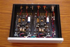
Also, just as a note in advance: using non-insulated RCA jacks is not recommended as this means the circuit common is connected to the chassis at multiple points causing ground loops. Also, having the power and input wires mixed up like that is likely to cause noise coupling from the power supply to the input, causing the circuit to hum.
Mr. Onion just posted a photo of his build to the Phonoclone forum, and I'm going to borrow that here as an example of what a functional and clean layout can/should/would look like.
Attachments
 That's it. Q1 and Q2 are installed backwards. While I have it apart, I will go ahead and rewire the boards in a more organized fashion. I was trying to keep the wires as short as I could, but I understand your point about the power wiring being so close to the output wires. I will also gets some insulated RCA jacks as long as I have it apart.
The delay will only make it sound sweeter when it is finally finished.
Thanks for the quick response.
John Cowling
Mr. Onion just posted a photo of his build to the Phonoclone forum, and I'm going to borrow that here as an example of what a functional and clean layout can/should/would look like.
*BLUSHES* Thanks for the compliment.
I did a few more changes today and re-measured everything.
I also measured for DC on the inputs with the C1 in place and got some minor measurements (~0.2mV) instead of a steady 0 like with C1 off the board (like the instructions say). Same with outputs.
Is that normal? (reminder I m talking about VSPS)
Thanks again
I also measured for DC on the inputs with the C1 in place and got some minor measurements (~0.2mV) instead of a steady 0 like with C1 off the board (like the instructions say). Same with outputs.
Is that normal? (reminder I m talking about VSPS)
Thanks again
Last edited:
I finished my Phonoclone 3 boards this morning (rev 35c). The power
supply checks out. The voltage at IN+ and IN- and OUT+ and OUT- are 0
V. V++ and V-- are 35 V. IC socket 1, however reads +.6 and -.6 V.
The only thing that was not by the book was I used at 2610 ohm
resistors at R2 when your Phonoclone calculator calculated 2500
because I had them on hand.
The cartridge is the MC that comes with the Clearaudio Concept turntable:
MC Cartridge / Pick-up:
Output Voltage (1kHz, 5cm/s): 0.4 mV at 5 cm/s
Channel Separation (1kHz): > 30 dB
Channel Balance (1kHz): < 0.5 dB
Tracking Ability: 80 μm
Tracking Force: 2.0 gram (+/- 0.2 gram)
Load Resistance: 100 Ohm
Load Capacitance: 100 pF
I used 100 and 0.4 in the calculator and it read 100 ohm for R1 and 2500 for R2.
I want to comment that you should not use the 100 ohm load restiance to calculate R1/R2 but the DC resistance of the coils. I do not see the DC resistance in the data above, it will most likely be much less as 100 ohm.
Ronald.
@dimkasta
1% of 400 mV is 4 mV, + 2 digits is +/- 6 mV. Anything less than that cannot be reliably measured with your meter, no. Anyway nothing to worry about.
@Ronald
John still has to get the transistors re-wired, and probably change the RCA jacks to isolated types. While he's at it, I suppose he has to replace R1 and R2 with - hard to know with out the DC coil resistance - but I'd try 10 ohms and 300 ohms respectively.
Good catch Ronald, thanks. What with all the stuff going on this weekend I missed that.
Thanks again
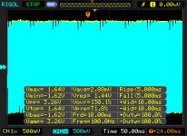
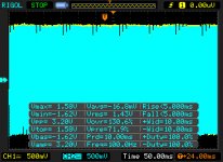
Maybe I should try to measure it using my scope.
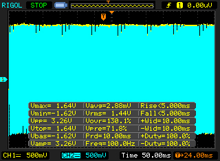
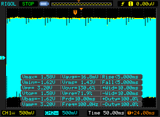
Speaking of which, could you please advise on how to get rid of the noise below? Peaks appear on 50 and 100Hz. 50Hz is probably noise coming from the rectifiers or the noisy transformer, not properly filtered by the crapola lelon caps on the regulators? (can t wait to get the mouser package with the nichicons, the torroids and the vishay bridges...) How about the 100Hz one?

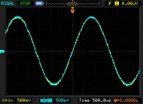
Also, at first glance, the output seems identical on both channels
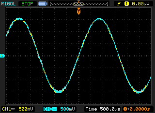
However, on a second read, the right channel seems to go ~60mV lower than the left on its top peak (could be cartridge anti-scate or azimuth issue?) Need to further investigate that. Too tired now.. need some sleep.
Thanks again
PS...damn... I need a signal generator too... and a high accuracy CLR meter...
Maybe I should try to measure it using my scope.
Speaking of which, could you please advise on how to get rid of the noise below? Peaks appear on 50 and 100Hz. 50Hz is probably noise coming from the rectifiers or the noisy transformer, not properly filtered by the crapola lelon caps on the regulators? (can t wait to get the mouser package with the nichicons, the torroids and the vishay bridges...) How about the 100Hz one?
Also, at first glance, the output seems identical on both channels
However, on a second read, the right channel seems to go ~60mV lower than the left on its top peak (could be cartridge anti-scate or azimuth issue?) Need to further investigate that. Too tired now.. need some sleep.
Thanks again
PS...damn... I need a signal generator too... and a high accuracy CLR meter...
Attachments
You also need to give a more detailed report! I have no idea what I am looking at. :/
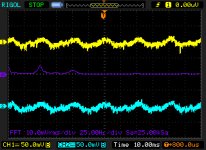
Is this really the output of your VSPS? With a cartridge or dummy load attached? Output noise will be very high if the input is left open circuit... but still I'm seeing in the first pic 20 mV of power supply ripple, which would be very high indeed. Normally there should not be any ripple visible on the output above the noise floor.
It looks like ripple to me, i.e. noise pickup from the rectified voltages, V++, V--.
Last edited:
- Home
- Source & Line
- Analogue Source
- The Phonoclone and VSPS PCB Help Desk