RJM, no way am questioning the RIAA's VSPS deviation.
On the contrary, I think it's very good, with very little deviation from the RIAA.
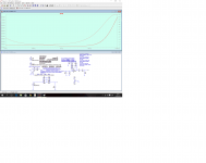
What I have shown in the graphs are possible responses to different combinations capacitances at the ends of their tolerances (+ -5%).
Today I have been measuring the capacitance of the capacitor that you have sent in the kit with a capacitance meter Fluke 15B.
Astonishing result: the variations are among 0.998nF and 1.012nF.
Adding skills I managed to C1: 0.998nF and C2: 3.01nF.
R5 is 733k and R4 is 110k.
To be perfect curve I add resistors or put them in parallel to reach 105k.
With the above capacitors it is thus the graph.
On the contrary, I think it's very good, with very little deviation from the RIAA.
What I have shown in the graphs are possible responses to different combinations capacitances at the ends of their tolerances (+ -5%).
Today I have been measuring the capacitance of the capacitor that you have sent in the kit with a capacitance meter Fluke 15B.
Astonishing result: the variations are among 0.998nF and 1.012nF.
Adding skills I managed to C1: 0.998nF and C2: 3.01nF.
R5 is 733k and R4 is 110k.
To be perfect curve I add resistors or put them in parallel to reach 105k.
With the above capacitors it is thus the graph.
Attachments
AndrewT, the small increase in the acute response is the effect of loading the cartridge with a little more resistance (56k) and the extension to higher frequencies is less load capacitance.
That was what I read in the articles I mentioned in the answer 3157.
and I checked in listening.
Acute appear softer, more extended further.
But all is debatable.
I'm not watching or listening to the frequency response of the preamplifier itself, which is flat, but the whole preamplifier with magnetic capsule and the slightly modified load.
Just I wanted to show something that maybe everyone already knew, which is as varied frequency response with only slight variations of capacitors; resistors; load the cartridge, etc.
Not to mention the influence on listening with the speakers; its position in the room; the size of the room; the shape of our pinna; our years with falling persepción treble, etc.
Music and its perception is very complex as to center only on the frequency response of a capsule or preamplifier.
Everything can be perfect, but if you suffer from hearing loss throw it all away.
Perhaps with graphics I posted I have carried misunderstanding.
Just as the audio hobbyist and the DIY I've been playing with different possibilities and then show them for their opinion (I am not an electronics technician. Just an enthusiast who 35 years ago built and break circuits). Queire not mean it is right.
But my intention is to build this phono stage as best you can.
I want it, of which I possess, which delivers better sound.
Cheers
(all the fault of Calvin, who was the one who suggested I use LTSpice)
Last edited:
Cartridge is not a RLC circuit ONLY. It has it's own mechanical properties including the needle.
Perhaps, using different load causes needle to be damped.
RIAA curve is defined via time constants and shows only "true sound spectrum" versus the output of the cartridge.
Of course, you can destroy this RIAA characteristics by plugging ie. huge capacity as cartridge load.
What u did was a try to model cartridge. I think in the same way as RJM: output from properly loaded cartridge (as specified by manufacturer) should be modified exactly as RIAA standard says.
A needle can't vibrate with really high frequency because of it's weight, friction etc. it's just an example which is not included in electrical simulation.
Assuming that input impedance of opamp is really high, you may consider input circuit separately.
You have no tools to check the quality of transferring vibrations from vinyl plate to the preamp input. You can only believe manufacturer, or write an email like "hey, wouldn't it be more RIAA like to change load?"
It would be a fun, if there is a plate only for testing purposes with written white noise on it! What a great idea I've just got ;-)
GRKZ, I think the issue has been the aim of this forum.
The preamplifier VSPS send RJM kit is an excellent piece.
What people do with the sound source or after the amplifier phono stage can be varied.
In pure electronic I agree that there are exactly, but in psychoacoustics is not written.
Do you test: simulate the cartridge Audio Technica AT440MLa whose characteristics are R: 3200 ohms and 490 mH, enter the Laplace formulated with time constants RIAA and then vary the simulated load.
You will see the items I mentioned in the answer 3157 have a point.
See the phono preamps reputable have keys to vary capacitance and load resistance.
Greetings and enough for me and it.
RJM to apologize for causing distortion to the central theme of this post, which is good VSPS construction.
AndrewT, the small increase in the acute response is the effect of loading the cartridge with a little more resistance (56k) and the extension to higher frequencies is less load capacitance.
That was what I read in the articles I mentioned in the answer 3157.
and I checked in listening.
Acute appear softer, more extended further.
But all is debatable.
I'm not watching or listening to the frequency response of the preamplifier itself, which is flat, but the whole preamplifier with magnetic capsule and the slightly modified load.
Just I wanted to show something that maybe everyone already knew, which is as varied frequency response with only slight variations of capacitors; resistors; load the cartridge, etc.
Not to mention the influence on listening with the speakers; its position in the room; the size of the room; the shape of our pinna; our years with falling persepción treble, etc.
Music and its perception is very complex as to center only on the frequency response of a capsule or preamplifier.
Everything can be perfect, but if you suffer from hearing loss throw it all away.
Perhaps with graphics I posted I have carried misunderstanding.
Just as the audio hobbyist and the DIY I've been playing with different possibilities and then show them for their opinion (I am not an electronics technician. Just an enthusiast who 35 years ago built and break circuits). Queire not mean it is right.
But my intention is to build this phono stage as best you can.
I want it, of which I possess, which delivers better sound.
Cheers
(all the fault of Calvin, who was the one who suggested I use LTSpice)
Alpuy,
I'll simply say that you've given me things to think about. I've always known that all cartridges aren't made equal, but I'd never considered how that might interact with a static RIAA preamp other than to say it probably has an impact. You've given me some examples where it might be audible and why.
More importantly, I like others suffer hearing loss in the treble range, and tend to like a stronger treble response in my gear. Enough that my 12 year old son notices. So a "flat" response or RIAA adjusted response may not suit me. I won't hear what the recording engineers intended unless I boost the treble response. Is that a bad thing? And if that's NOT a bad thing, then why would we build absolutely flat frequency response gear (including the assumption that the gear that preceeds it was designed to give flat response)? Why would I strive for something that won't give me the listening experience the musicians and engineers intended?
I've often thought that I'd like to profile my hearing curve and build gear that compensates. Maybe that would be ideal...
OK, enough of that.
all 5 of your plots show a crippled treble response.
What have you done that creates this?
For the circuit diagram ALPUY posted, it looks like an inverse RIAA signal generator feeding into a series LC stage which I suppose is to model the cartridge. The increasing impedance of the inductor at high frequencies against the input impedance of the VSPS (and the cable capacitance) causes the high frequency rolloff.
I can't say for sure either way, but its probably a reasonably fair approximation of the actual frequency response of the cartridge as I don't think MM types go much above 20kHz.
My original point still stands though: you shouldn't compensate a phono stage for a specific cartridge since in principle the cartridges are already compensated to work with an ideal RIAA eq. I mean, that's what the cartridge designer assumes he/she has to work against: the basic 47k input impedance, a standard range of cable capacitance, and the usual RIAA curve.
Ok, so ALPUY's capacitance measurements seemed a little too good to be true so I measured a batch of 10 here on the hp 4192A, at 100 kHz.
I get a spread of 3%. Highest was 1.0163 nF, lowest 0.9855 nF. Pretty much what you'd expect for 5% parts given the limited number of samples.
@ALPUY, You got lucky!
I get a spread of 3%. Highest was 1.0163 nF, lowest 0.9855 nF. Pretty much what you'd expect for 5% parts given the limited number of samples.
@ALPUY, You got lucky!
Fluke perhaps not as precise as HP.
So all I'm very happy with the values you have sent (the lower 0.998ny the largest 1.012n).
Greetings and sorry for the misunderstanding that I have caused to load the cartridge. I've only read article Hagerman and others I've mentioned. I applied and I found my ears better. I have not questioned your VSPS.
Hello. Now out of rare theories that are out of the loop phono stage. I ask about some things that would make, and with respect to the power supply.
I'm going to ride in a remote box with an umbilical cord of 2 meters.
The questions:
1-scotchy diodes can be used instead of common ?.
2- You can add high-capacitance capacitors (10,000 uF) before exiting through the umbilical cord to phono stage ?.
3. The umbilical cord must be shielded, and in that case, the mesh where it is attached to earth, at the end of the end PSU or phono stage ?.
Thanks and regards.
For those who are searching for a "good enough" way to measure capacitance, I have bought https://www.sparkfun.com/products/9485 and it worked very well for me when matching 5% capacitors to the tight tolerances needed for an RIAA network.
The fact that it costs less than 15$ is also an added benefit, especially considering the cost of a Fluke meter...
The fact that it costs less than 15$ is also an added benefit, especially considering the cost of a Fluke meter...
I bought a general purpose ATmel mega328p based instrument.
But it reports identical outputs for what are clearly different devices.
It seems that the way it is set up, that it uses too few bits to differentiate small differences in the parameters that that it reports. And then jumps to the next value for what are much higher parameter values
How well does your kit differentiate small differences?
I don't know if I understand your question well, by the capacitance meter kit reports values down to the pF.
I have even tried measuring the same capacitor under different conditions (temperature & PS voltage, etc..) and the results have been pretty consistent, with readings not fluctuating more than a couple of points between extremes for the same 33nf capacitor (temperature of 10 degrees C vs temperature of 40 C)
I have even tried measuring the same capacitor under different conditions (temperature & PS voltage, etc..) and the results have been pretty consistent, with readings not fluctuating more than a couple of points between extremes for the same 33nf capacitor (temperature of 10 degrees C vs temperature of 40 C)
The website shows a 4digit LED display and autoranging.
What is the reading for the 33nF capacitor?
What is the reading for 33nF||150pF? 33nF||100pF? 33nF||47pF? 33nF||22pF
Is the lowest (least significant bit or resolution) reading 1pF?
What is the reading for 10pF and for 22pF? and for 10pF+22pF? This last should be ~6.9pF
Looking at the comments re 5% tolerance resistors, makes me wonder if R14 through to R18, should all be +-1% tolerance, or better.
What do you think?
Last edited:
Friends, I bought a similar item. Based on this meter I measured the resistors and capacitors Richard sent me the kit VSPS 300. For example, a capacitor of 1 nF network RIAA gave me 920 pF-960pF- 980pF etc. all for that range.
Measured with a Fluke 15b 998pf- 1.012nF 1.008nF ect.
1nF much closer to what they should being.-
I made measurements with a Fluke (paid) because Richard said "That's Assuming your meter can measure to better than 2.3% absolute accuracy ... which if made by Fluke ITS hp or we can suppose it does. If it is some $ 15 random piece of junk you picked up off Ali Express STI Basically trustworthyness for accuracy is zero. ".
I multimeter compradoes this
http://es.aliexpress.com/item/Free-S...OrigTitle=true
The website shows a 4digit LED display and autoranging.
What is the reading for the 33nF capacitor?
What is the reading for 33nF||150pF? 33nF||100pF? 33nF||47pF? 33nF||22pF
Is the lowest (least significant bit or resolution) reading 1pF?
What is the reading for 10pF and for 22pF? and for 10pF+22pF? This last should be ~6.9pF
Looking at the comments re 5% tolerance resistors, makes me wonder if R14 through to R18, should all be +-1% tolerance, or better.
What do you think?
I was lucky enough for the resistors to be pretty tightly matched to the BOM values (at least according to my DMM), the only one that was out of spec was replaced by a 1% resistor I had lying around.
I will run the tests you mentioned and revert back with results.
I'm interested to see how it will fare.
Regards
- Home
- Source & Line
- Analogue Source
- The Phonoclone and VSPS PCB Help Desk