Input Capacitors for Headphone Amps
It actually made me confused. Otherwise I would have finished after checking that
1/(2pi*(33k||10k pot || 10k load)*2.2uF) is lower than 20 Hz.
It actually made me confused. Otherwise I would have finished after checking that
1/(2pi*(33k||10k pot || 10k load)*2.2uF) is lower than 20 Hz.
Yes, that gives ~16.6Hz for the F-3dB filter roll-off frequency.
It will start to affect frequency response from ~160Hz and phase is being affected from ~400Hz.
Drop that by a decade to reduce both those effects and you may be more pleased with the resulting sound.
What is the rule? Can I ask u for deriviation/link?
-3 dB at 16-20Hz is not crucial for me as my (PC) speakers are limited by 45 Hz and have separate bass control on the subwoofer. But I would like to make it possible to plug in any amp/speakers.
I can't drop RC constant ten times. I can't use 100 kHz potentiometer. Even if I use ~30-47 k, 33k in parallel will divide it by 2. I assume that RJM will say that feedback loop actually introduces some distortion in phase and will be laughing that I ask for such details while using cheap WiMA 2.2 uF output caps
")
Anyway, I have never expected that simple volume control can be somehow compliceted
Read about my experiments and reported repeatedly on this Forum, for how I arrived at that ~2Hz roll-off frequency.
It confirmed for me why MANY amplifier manufacturers state an F-1dB bandwidth starting @ ~4Hz.
For me, setting the frequency any lower than 4Hz could not be heard and I simply added one more octave to allow for tolerances and source impedance effects.
BTW,
the DC blocking capacitor should be at the input to the amplifier.
The vol pot should be on the other side of the DC blocking capacitor. In that location the vol pot becomes the Source feeding the DC blocker+amplifier.
I think that it is nicer to delete offset at the output (not remove capacitor). I can't be sure if my amp is AC coupled. It should be.
Moving 10k potentiometer before 2,2uf capacitor results in very narrow bandwidth (as it becomes a low pass filter...). And roll-off freq depends on the pot's axis turn angle.
Yes, I would like to move coupling -3dB up to 2-4 Hz.
Back to the original project:
Original VSPS has ~47 ohm output impedance (correct me if I am wrong).
But 33k resistor in parallel with load (let's say 10k or 20k) creates filter with corner freqency:
f_c = (2pi * 33k||10k * 2.2u)^(-1) = 10 Hz
So in original RJM circuit you encouter phase effects at 100-200 Hz which possibly can be audible. Only plugging infinite impedance instead of 10k makes this roll-off near 2 Hz.
I have not worked out any solution to simple volume control yet ;-(
It's tempting me to make some simulations with this circuit.
OK,
after some reasearch:
Filters and Phase Shifting
Coupling Capacitors
It seems that phase shift of signal frequency components is not audible.
Loudspeaker and room introduces much more shift than simple filter.
In some cases, high pass filter with roll-off at ~20 Hz may prevent damaging loudspeaker by attenuating lower frequencies.
I will stick with shunt volume controller.
VSPS output -> 10 kohms resistor -- (output to PC speakers amp) -- variable resistor (two terminals of 10k logarithmic pot) -- gnd
In this case impedance seen from VSPS output is at least 10 kohms (because "shunt volume controller" has 10k resistor in series with VSPS output). Then:
f = (2pi 33k||10k 2uF)^-1 =~10 Hz
Can someone with greater experience than me approve this solution?
Think of the VSPS as the VSPS.
Normally the VSPS has an output impedance of 47 ohms. This drives the interconnect cable capacitance and the input impedance of the amplifier. It provides a low impedance shunt for noise currents.
If you put a volume control on the output of the VSPS, the impedance increases depending on the type and volume setting use. The frequency of the LP filter with the cable capacitance decreases. The noise currents induce larger voltages.
The output impedance should be below 1k. Larger values will start to cause problems.
If you move the volume control to the amplifier side, all these problems go away as the output impedance of the VSPS returns to 47 ohms. This is the only good solution to the problem, anything is a tradeoff.
However, a 10k pot on the VSPS output will, provided the volume setting is kept low, not be too serious a problem, given that you are only using Creative PC speakers anyway. Think of it as a passive preamp built into the VSPS chassis.
Keep in mind, that 47 ohm output impedance is achievable only for very high frequencies. For -3dB (~2 Hz) (no load attached to VSPS):
|1/(j2pifC)| ~ 30 kohms so output impedance of VSPS is approximately 15 kohms! For much higher frequencies you are right, capacitor can be considered as being shorted.
I forgot about that too.
So it affects all projects incorporating your preamplifier! I may do output impedance simulation for you. If you wish, of course.
I've just checked Leapi 2020+ amplifier (I've heard it's one of the decent quality for that really low price). It has 50k volume pot at input and 3,3uF & 10k HP filter. If all amps have input stages bulit like this one - why not remove 2,2uF coupling cap and 33k resistor?
I know that I'm quite stubborn. But hope that it leads me to better understanding of audio circuits and provide you with some fresh (despite that I'm a beginner) thoughts on your project.
Good afternoon. RJM, I received today VSPS kit 300 dual mono.
Very good looking and well built the PCB.
I did count parts kit and everything is perfect.
But I measured the components of the RIAA network and has given me:
R5 732k and 735K
R4-110k and 110k
C2-3 capacitors have grouped so that they are in 2.777ny 2.784n
C1- 0.920n and 0.920n.
In view of these values I've done LT SPICE simulation and have found that the curve would fit better if I take R5 to 800k (even with some more serious dot between 20 and 100Hz).
This may be true or impair the performance of this prestigious preamplifier ?.
I have not even begun to build.
When I finished I upload photos. Regards. Joseph.
Estoy usando cartucho Audio Technica AT 440 MLa, cargado con 47k y 92pF (capacitancia de cable desde brazo hasta conector).
Fabricante aconseja 100pF y 47k.
Last edited:
What is your multimeter?
Every measurement has it's uncertainty. I would check device class in this range (capacity measurement). All values measured by you are lower than nominal ones. I assume (despite that it's really small population) that there might be just systematic error. Do all caps have 1% tolerance?
Every measurement has it's uncertainty. I would check device class in this range (capacity measurement). All values measured by you are lower than nominal ones. I assume (despite that it's really small population) that there might be just systematic error. Do all caps have 1% tolerance?
Hello. The meter was purchased from China.The manufacturer has exatitud to 0.1 ohms and from 30pF it says.
http://es.aliexpress.com/item/Free-...-MOS-LCR-NPN/2044583768.html?isOrigTitle=true
The important thing is equal values on both channels.
Cheers
http://es.aliexpress.com/item/Free-...-MOS-LCR-NPN/2044583768.html?isOrigTitle=true
The important thing is equal values on both channels.
Cheers
Keep in mind, that 47 ohm output impedance is achievable only for very high frequencies. For -3dB (~2 Hz) (no load attached to VSPS):
|1/(j2pifC)| ~ 30 kohms so output impedance of VSPS is approximately 15 kohms!
Yes, the rising impedance of the coupling capacitor at low frequencies acts against the impedance of the following stage to form a high pass (DC blocking) filter. That's ... what it does. How it works. I'm not sure how to take this except as a statement of the obvious.
If all amps have input stages bulit like this one - why not remove 2,2uF coupling cap and 33k resistor?
Because ... they ... don't. Murphy's Law says you cannot design for the 99% of safe cases, you must protect against the 1% of dangerous ones. The VSPS and especially the Phonoclone can, due to the high DC gain, put relatively large and potentially dangerous (when used with a DC coupled amp) offsets on the output unless a coupling capacitor is used.
But I measured the components of the RIAA network and has given me:
R5 732k and 735K
R4-110k and 110k
C2-3 capacitors have grouped so that they are in 2.777ny 2.784n
C1- 0.920n and 0.920n.
In view of these values I've done LT SPICE simulation and have found that the curve would fit better if I take R5 to 800k (even with some more serious dot between 20 and 100Hz).
As can no doubt see from your sim, increasing R5 adds a "bump" in the mid-bass response around 50-60 Hz. You are welcome to try increasing the resistance to 800k. This is only a ~5% (i.e. within the spread of the capacitance values) increase and the change in the response will be just-barely audible.
Basically, you are partially compensating for the (supposed) slightly lower than expected capacitance values. That's assuming your meter can measure to better than 2-3% absolute accuracy... which if its made by Fluke or hp we can imagine it does. If it is some random piece of $15 junk you picked up off Ali Express its trustworthyness for accuracy is basically zero.
Last edited:
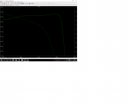
Hello. Before starting to assemble the plates VSPS 300, it has occurred to me to five different simulations with maximum variations of the capacitors C1 and C2.
After seeing the results I wonder if it would be convenient to use tolerances of + - 1% instead of + - 5%.
1- C1 with +-0% variation
C2 with +-0% variation
2- C1 with +5% variation
C2 with +5% variation
3- C1 with -5% variation
C2 with -5% variation
4- C1 with -5% variation
C2 with +5% variation
5- C1 with +5% variation
C2 with -5% variation
these differences are audible in graphics or do not need to carry the values of C1 and C2 1%?
I clarify that I have loaded the cartridge with magnetic 56kohms because I see that it improves response in acute. Carries increased to 4300 Hz with 9800 Hz 47kohms, and there is less attenuation 20khz.
92 pF load is the cable. If the increase means an increase in acute and 20kHz greater attenuation it occurs.
Maybe I'm exaggerating, but my desire is to get the best performance of the phono stage. Regards.
(the last graph is with C1 and C2 with 0% variation and the cartridge loaded with 47 k ohms)
Attachments


Last edited:
I would never do it this way. Of course, you can make parametric simulation, but again - you have to be sure about all resistors' values in the circuit.
Personally, I would focus more on shielding and power supply. Our aim is to get really good sound and have some pleasure while listening to music. Feedback loop is only part of the success.
If you really want to know your preamp's parameters - you'd better plug your assembled phono preamp into spectrum analyzer.
I doubt if 0.5 dB difference in transfer function can be heard.
What I learned so far is also that amplifier and speakers are also modifying sound.
I would also load cartridge with resistor that is suggested by manufacturer. There is no accurate cartridge model in LT Spice.
Just assemble and have fun ;-)
GRKZ Hello, I read some articles about the influence of the load impedance and capacitance of a cartridge.
I tried what these articles say and really notice the difference in the, softer and extended down the sharp end I leave 8I capacitance cable only) and increasing some resistance. Regards.
Hagerman Technology LLC: Cartridge Loading
Cartridge loading explained - Vinyl Engine
Load the Magnets!!! - [English]
Magnetic Phono Pickup Cartridges
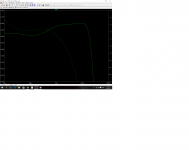
A few, possibly very few, report hearing response aberrations as low as 0.1dB
0.5dB seems to me excessive.
I note that the flattest is no.5 with C1 @ 105% and C2 @ 95% of the recommended values.
Is this because you have loaded the cartridge in an unusual way?
Why is the treble response crippled in all the plots?
Again, is this due to unusual loading?
0.5dB seems to me excessive.
I note that the flattest is no.5 with C1 @ 105% and C2 @ 95% of the recommended values.
Is this because you have loaded the cartridge in an unusual way?
Why is the treble response crippled in all the plots?
Again, is this due to unusual loading?
So is Andrew, Audiotechnica recommended 47kohms and 100 pF.
I have done the simulation with this burden and find that there is a small rise about 4500 kHz, then an important drop in acute higher.
After reading several articles on the effect of capacitance and load resistance in the cartridges, I tested with less load capacitance (92 pF in my case it is the total capacitance of the cable measured without the capsule) and 56kohms. The simulated response and "heard" is much better and much more enjoyable, if those sharp shrill, and com more details.
If you read my speeches, they will seem exaggerated, and really are, but I really want the circuit I bought render the best you can. Regards.
I'll get really measuring resistors and capacitors of the RIAA network with a reliable multimeter as RJM told me that I own is not reliable (for resistors if reliable because I have compared to another).
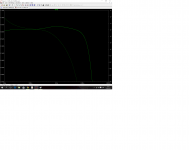
What causes the HF rolloff in your simulation? Are you building in the frequency response of the cartridge somehow?
I suggest instead that you look at the frequency response of the VSPS as an audio component and nothing more. A phono stage must be designed to give the RIAA response for a perfect input signal. The phono stage should not try to second guess the source by compensating in advance for the capacitance of the input cable, for example, or the impedance of the cartridge. It is the job of the cartridge manufacturer to make a cartridge that, when working against the recommended load (47k, and possible a load capacitance), it generates a signal that is close to this perfect input signal the phono stage was designed to work against.
I recommend you simulate the VSPS response with an ideal voltage source input.
- Home
- Source & Line
- Analogue Source
- The Phonoclone and VSPS PCB Help Desk