EDIT EDIT EDIT:::::
OK busy testing, and ...still no better
What does too little gain sound like?, the breakup is quite apparent at the fading bits at the end of songs (but not limited to this).

Metallised polyester vacuum evaporated aluminium electrodes
Self-extinguishing encapsulation material to UL 94V-0
Suitable for bypassing, signal coupling and general purpose applications requiring high reliability
Capacitance tolerance: ±5%
While we are on caps, may I ask why we don't use any decoupling caps close to the pins here?
OK busy testing, and ...still no better
What does too little gain sound like?, the breakup is quite apparent at the fading bits at the end of songs (but not limited to this).
Metallised polyester vacuum evaporated aluminium electrodes
Self-extinguishing encapsulation material to UL 94V-0
Suitable for bypassing, signal coupling and general purpose applications requiring high reliability
Capacitance tolerance: ±5%
While we are on caps, may I ask why we don't use any decoupling caps close to the pins here?
Are the voltages both + and - 15VDC?
What opamp did you use? Do you have another that you could insert into the socket?
Do you have another phono stage to compare?
What opamp did you use? Do you have another that you could insert into the socket?
Do you have another phono stage to compare?
Well it is the VSPS (Very simple phono stage..but good sounding ;-) ..but you can always do that yourself if you like.may I ask why we don't use any decoupling caps close to the pins here?
I used NE5532... sadly no, it was the first thing I built other than the REV C, using an opamp, since very long ago...
I will get the OPA2134 and required caps (sigh) to do the other version... I'm pretty sure the chip is good.
yeah got one on the sansui integrated amp... will give it a listen a bit later... must connect speaker cables etc...
I will get the OPA2134 and required caps (sigh) to do the other version... I'm pretty sure the chip is good.
yeah got one on the sansui integrated amp... will give it a listen a bit later... must connect speaker cables etc...
Should be fine. Just checking.I used NE5532...
I used the OPA2134 in the low impedance version..still sounded great.
OK, switched over to the OPA chip and suggested resistors...
It sounds better but still very grainy...
I used
R2 2k2
R3 6k8
R4 330k
R5 2M2
Could someone please give me resistor combinations to increase and decrease gain by one so that I can learn what its doing wrong... !!!!!!!!!
Circuit no longer hums, one good thing from the OPA it seems, and the distortionseems more evenly dispersed rather than just in the bass and treble...
Could it be that the REV C is too sensitive for the output of this phonopre...? Would changeing the gain help then?
Nordic,
Your problem is most likely related to the power supply, not the RIAA loop.
The LoZ (or HiZ) versions and 40dB of gain, as you have built, will work fine, and should be stable, with your op-amp and cartridge.
Try wiring the bypass caps directly form the opamp power pin to the signal output. Check that the DC voltage going into your LM7815 and 7915s is above 18-19 V. Check that you aren't using a non-polar cap for output coupling.
Unfortunatey your posts havent improved any. No details on layout or power supply, no measurements of and AC or DC voltages in the power supply. It took about three posts for me to even figure out you were using a Grado cartridge. In short, still doing your upmost to make it extremely hard for anyone to help you.
Richard
Sadly I have no digital camera....
I have copied the layout as provided on http://www.geocities.com/rjm003.geo/rjmaudio/diy_pho5.html
PSU consists of 4 x 250uf caps as per instruction...+.1uf caps just after the regulator. I am getting 24.1V between V+ and V- inputs on IC socket. Also, I am using 7812 and 7912 (not 15) as per instructions....
Not sure about the cap you suggested... do you mean from output pin on the IC to the V+ pin?
Erm why? the instructions says, C3 4.7µ, Output coupling. Must be non-polar......
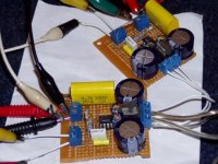
I got that poly cap in there as per the picture a few posts back...
Just confirm if you mean for this to be an electrolytic.... (I got some NP electros I can use in there...)
I have copied the layout as provided on http://www.geocities.com/rjm003.geo/rjmaudio/diy_pho5.html
PSU consists of 4 x 250uf caps as per instruction...+.1uf caps just after the regulator. I am getting 24.1V between V+ and V- inputs on IC socket. Also, I am using 7812 and 7912 (not 15) as per instructions....
Not sure about the cap you suggested... do you mean from output pin on the IC to the V+ pin?
Check that you aren't using a non-polar cap for output coupling.
Erm why? the instructions says, C3 4.7µ, Output coupling. Must be non-polar......
I got that poly cap in there as per the picture a few posts back...
Just confirm if you mean for this to be an electrolytic.... (I got some NP electros I can use in there...)
Erm why? the instructions says, C3 4.7µ, Output coupling. Must be non-polar......
Yes, must be non polar, but not a non polar electrolytic!
I recommend a good MKP quality, some WIMA will do the job well.
BTW: why, Richard, do you still use such a high value? The resulting roll off with a following 22k input will be 2 Hz.
You could insert a 1uF cap without any remarkable loss in the bass area. Even with a following 10k stage, you will be on the fine side with 2.2uF.
I always use 0.47uF in conjunction with my 50k amps. The roll off is about 7Hz.
Franz
Ta Franz, will play around with the output cap a bit but I still think there is a simpe mismatch between the VSPS and the REV C, unless I made a stupid soldering error somewhere..
I have now added 10nf from power pins to ground as per datasheet, and added 1000ufd before the regulator...
Still no joy, will now play arround with some output caps...
Does R2 and R3 set the gain?
I have now added 10nf from power pins to ground as per datasheet, and added 1000ufd before the regulator...
Still no joy, will now play arround with some output caps...
Does R2 and R3 set the gain?
Translation from South African english to international english..Ta Franz
Thanks Franz
I am getting 24.1V between V+ and V- inputs on IC socket. Also, I am using 7812 and 7912 (not 15) as per instructions....
Not enough..you should get 30VDC between V+ and V-. In other words....around 15vdc between v+ and 0 and
-15vd between 0 and v-
12V rectified gives about 15.xV, which then gets regulated to 12V, I got some thicker wire to redo the ground line with too now... was using doubled up wire for it... as I do notice some hum that increases with volume...
I just put the thingy down for a bit, before it breaks my spirit...
Can it work with only rectification and no regulation? that would give me a few more volt.
I just put the thingy down for a bit, before it breaks my spirit...
Can it work with only rectification and no regulation? that would give me a few more volt.
Franz,
Not everyone has a high input impedance pre-amp. 4.7uF is good for anything down to 600 ohms in a pinch, and using the BG N it takes up no appreciable space. As I've said several times before, lower values are perfectly acceptable as the load, size consideration, and availability dictate.
Nordic,
A 2x12V AC transformer is fine. This will produce about +-17V DC, which then regulates to 12V DC after the 7812s.
You've only got 15V DC unregulated for some reason. Depending on the ripple, thats actually a fraction low for the input of the 7812s, though unlikely be a problem ... also its a sign perhaps that the circuit is drawing more current than it should or that something else isn't quite right.
Bas,
Nordic was talking about the regulated voltage between the op-amp power pins, you were referring to what I call V+ and V- on the PCB, the unregulated input voltage.
/R
Not everyone has a high input impedance pre-amp. 4.7uF is good for anything down to 600 ohms in a pinch, and using the BG N it takes up no appreciable space. As I've said several times before, lower values are perfectly acceptable as the load, size consideration, and availability dictate.
Nordic,
A 2x12V AC transformer is fine. This will produce about +-17V DC, which then regulates to 12V DC after the 7812s.
You've only got 15V DC unregulated for some reason. Depending on the ripple, thats actually a fraction low for the input of the 7812s, though unlikely be a problem ... also its a sign perhaps that the circuit is drawing more current than it should or that something else isn't quite right.
Bas,
Not enough..you should get 30VDC between V+ and V-.
Nordic was talking about the regulated voltage between the op-amp power pins, you were referring to what I call V+ and V- on the PCB, the unregulated input voltage.
/R

Parts Selection Help
I am a Noob planning to build the Hi-Z VSPS. I need help when it comes to sourcing parts. I like working with Mouser Electronics as it is easy to find components and they have no minimum order size. I am planning on using the following parts:
All resistors except R5 - 2.2M will be Vishay Dale 1% metal film
R5 will be a KOA Speer 1% metal film (Vishal/Dale from Mouser stops at 1M)
C1 - WIMA FKP 5%
C2 - WIMA MKP 5%
C3 - Kemet Solid Dipped Radial Tatalum 50V 10%
U1 - STMicroelectronics Single Lo-Noise JFET TL071A
Data Sheet at http://www.mouser.com/index.cfm?han...uctid=323982&e_categoryid=268&e_pcodeid=51123
I am initially going to use a regulated power supply that I built from a kit (Wellborne PS1) for another project. It will supply +- 12V.
If I like how this turns out, I will build an unregulated supply and put the regulation on the VSPS boards. I will also try other Op Amps such as OPA227 or OPA228.
Am I making any major mistakes with my parts choices? I am especially concerned with C3 as I undestand the coupling cap is extremely important since it is in the signal path.
Thanks for any input.
Good that you asked, it could have been a bit of a disaster otherwise.
C3 must be non-polar. Either a non-polar electrolytic or a normal film&foil type. Tantalum caps are polar.
Working from Mouser, can you find something from Wima in the MKS range near 2.2 uF? That will do the job.
Other than that, your choices are acceptible given the limitations of your source.
/R
I'm going away to Sapporo for a week. A vacation so no audio and no internet. See y'all later.
- Home
- Source & Line
- Analogue Source
- The Phonoclone and VSPS PCB Help Desk