An externally hosted image should be here but it was not working when we last tested it.
An externally hosted image should be here but it was not working when we last tested it.
An externally hosted image should be here but it was not working when we last tested it.
An externally hosted image should be here but it was not working when we last tested it.

power supply working
it aint pretty but it works.
An externally hosted image should be here but it was not working when we last tested it.
now just to get the phonoclone and sapphire together.
Does anyone know what Bibio has used to connect the transformer winding wires to the pins of the rectifiers? Are they some sort of crimp join?
Thanks in advance
") I'm trying to make my PSU neater - tried soldering wires directly to pins and did a terrible job, then I tried varoboard as an interface, the holes in the varoboard were too small and when I tried to drill them out ever so slightly to make them bigger, the copper strip started coming off :/
I'm trying to make my PSU neater - tried soldering wires directly to pins and did a terrible job, then I tried varoboard as an interface, the holes in the varoboard were too small and when I tried to drill them out ever so slightly to make them bigger, the copper strip started coming off :/As wirehead.be said, looks like a direct solder + heatshrink.
Neatness for neatness sake is not worth pursuing. It doesn't have to be done pretty, as long as it is done well. Sometimes the best method is actually the ugliest.
In this case, the most reliable connection for the bridge rectifiers is a wire soldered directly to the leads. Some of the heavier bridges have 5 mm tabbed leads, and obviously a commercial build would have a dedicated circuit board, but screwing the recitifers legs-up into the case, and soldering the wired to the leads biblio did is perfectly acceptable, indeed recommended.
The heavier leads of the rectifier means you need a more powerful iron (or higher temp setting) to do this without making a mess.
Last edited:
still not finished my amp/clone as i run into problems :-(
anyway, i used terminals part # 3-8070 from here for connecting the transformers to the bridge rectifiers.
in hindsight though i should have just used some screwdown blocks.
if i could make pcb's then i would have done it that way using screwdowns.
i'm hoping to get back on track soon
the phonoclone is working but the headphone amp is not and i have decided that i'm going to do things a little different as regards to power supply or i might just plug the phonoclone into an integrated amp and use the headphone amp in that.
hi Richard, its the sapphire. i've more than likely burgerd it up somewhere along the line.
i haven't a clue what i'm doing.. lol
i'm going to be getting back into putting this thing together very very soon and i'm going to have a go making some PCB's for myself to make things easier to hook up. had a look on the tube and it looks fairly simple.
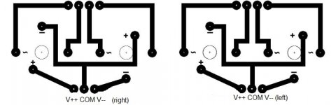
the PCB i'll be trying to make is for connecting the transformers/rectifiers/output. this is what i have come up with so far.
![IMGDEAD]](/community/proxy.php?image=http%3A%2F%2F%5BIMGDEAD%5Dhttp%3A%2F%2Fi44.tinypic.com%2F2s7jkzp.jpg%5B%2FIMGDEAD%5D&hash=f09a849483c64d369326b1a3e1176ec1)
i haven't a clue what i'm doing.. lol
i'm going to be getting back into putting this thing together very very soon and i'm going to have a go making some PCB's for myself to make things easier to hook up. had a look on the tube and it looks fairly simple.
the PCB i'll be trying to make is for connecting the transformers/rectifiers/output. this is what i have come up with so far.
Feel free to run it past me in detail, on the Sapphire thread or by email.
The PCB traces above look basically right, but I don't follow what you are doing with the output V++ COM V--, there are pads which don't seem to be connected to anything. The attached revision would seem to be sufficient...
The PCB traces above look basically right, but I don't follow what you are doing with the output V++ COM V--, there are pads which don't seem to be connected to anything. The attached revision would seem to be sufficient...
Attachments
LEDs. I should have guessed...
No output? Okay. That's an observation rather than an analysis. It doesn't give me anything with which to help you.
The procedural flowchart should go something like this.
No output. -> Damn! Okay, is the input connected and playing? Yes. Do I get any hiss with the volume turned up suggesting the unit is powered up and the output at least has continuity to volume pot (input) and the unit is working? Nothing. Alright, things are borked: Shut down, take a break, and prepare to tackle this point by point.
Normally, you go through this before even thinking about passing an audio signal though a new built, but alright, assuming you ignored that advice and went with just the tried and true "smoke test" before trying to listen, here is the checklist...
1. Visual inspection. Double check parts values, orientation, and connectivity.
2. Power up. Smoke test. Check the power supply, V++ and V-- to COM for the correct voltages. +/- 18 V
3. Check the internal circuit voltages from the op amp power pins to COM. +/- 10 V
4. For the sapphire, check that the transistors are getting warm, also, the voltage across the output emitter resistors should give a reasonable bias current, as I = V/R. For 14s boards, its 20-30 mA, or 10 mV across the resistors. (Use the "mV" setting on the voltmeter to get an accurate reading.)
If any of those checks fail, and for any reason you can't figure out why they failed, then its time to come and talk to me.
The Sapphire circuit is reasonably robust. The main challenge is getting the p and n transistors in the right places, the right way 'round.
Last edited:
one step closer to getting things done.
my very first attempt at making PCB's. it was fun
awaiting an order from RS and i'll get things together.
my very first attempt at making PCB's. it was fun
An externally hosted image should be here but it was not working when we last tested it.
awaiting an order from RS and i'll get things together.
question on 'hook up' wire for the audio paths between each board and in/out sockets. my build is Phonoclone3 and Sapphire in same case.
i have at hand lots and lots of Cat5 cable also a fair old whack of ribbon cable i also have a fair amount of figure 8 audio cable.
or should i go and buy some nice proper stuff and if so what would people recommend?
i have at hand lots and lots of Cat5 cable also a fair old whack of ribbon cable i also have a fair amount of figure 8 audio cable.
or should i go and buy some nice proper stuff and if so what would people recommend?
Cap Rack and burn in time question
I just ordered some rel-Cap RTE's and Muticap RTX to try in my VSPS 300. I bought a small transformer and will build a cap rack to burn in the caps before install. There are numerous warnings from user's about the RTX's that say these need 250 hours before they sound right. Will the cap-rack speed up this process or should I just plan on a good ten days of burn in?
I just ordered some rel-Cap RTE's and Muticap RTX to try in my VSPS 300. I bought a small transformer and will build a cap rack to burn in the caps before install. There are numerous warnings from user's about the RTX's that say these need 250 hours before they sound right. Will the cap-rack speed up this process or should I just plan on a good ten days of burn in?
ahh so i might end up with more rumble coming threw. also i suspect that it will effect the top end as well?
think i'll get everything up and running first then start playing with caps.
i know its a nono but i have put trailing leads on the phonoclone/sapphire boards that plug into a daughter board, only reason i have done this is to make it easier for pulling things apart in the future. i might have put far too big headers on though. lol
one other thing i have come across is you might want to look at putting a mounting template or the mounting sizes on the BOM for the Sapphire and the Phonoclone.
- Home
- Source & Line
- Analogue Source
- The Phonoclone and VSPS PCB Help Desk