I believe the ODA DAC will match or outperform its two closest competitors--AMB and Twisted Pear--in most ways for substantially less money...
Great plans, nice to have more competitors on the market
")
Btw, have you already measured the TP DAC? There was some guy who was willing send it to you (here).
@forsakenrider, the current DAC daughter board for the ODA can be used stand-alone from USB power with a line level (not headphone) output. It doesn't use the ancient TI PCM2xxx series USB chips as they don't support 24 bit operation over USB and have mediocre performance in some areas.
I believe the ODA DAC will match or outperform its two closest competitors--AMB and Twisted Pear--in most ways for substantially less money. Like the O2 it will offer maximum performance at the lowest possible price instead of focusing on the the latest FOTM or esoteric components. And unlike AMB, Twisted Pear, Schiit Audio, Matrix, Audinst, AudioGD, numerous eBay products, etc. the performance will be fully documented on professional equipment.
So the DAC board for the ODA will be your custom design? Any SMT components involved?
So the DAC board for the ODA will be your custom design? Any SMT components involved?
He's had some discussions with the Audio Widget(open source design) guys, and if you've read his Blog, you know his opinion on SMT already..
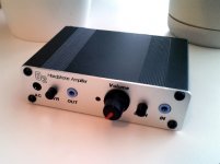
I finished the first of two O2 amps today. All of the initial tests went well and when I was finally able to plug in some "non-throwaway" headphones and listen to some FLAC files I came away very impressed! THANK YOU, RocketScientist, for sharing your design expertise with the community and your many, many hours to test and document the amp every step of the way.
I find the O2's sound to be very transparent and easy to listen to. I've tried some IEMs and Beyer DT-770 80 ohms headphones, but haven't yet plugged in my LCD-2 Rev. 2 headphones (need to get an 1/8" to 1/4" adapter).
BTW, the front panel from FPE is a perfect fit and alignment of all the machined holes is very accurate. They do great work...I look forward to seeing their facility in January at a Seattle Head-Fi enthusiasts meet.
An image of my first O2 amp is here:
Attachments
@RocketScientist - when you do the desktop design, would you consider including twin output stages, each with separately-adjustable gain? It would be very useful to be able to plug in 2 sets of headphones - bit more sociable!
I'm assuming there will be plenty of board space to play with; of course, anyone who only wanted one output could then leave the unwanted components off.
I'm assuming there will be plenty of board space to play with; of course, anyone who only wanted one output could then leave the unwanted components off.
greenalien - FWIW, you could even do that right now with the existing O2 by putting two of the O2 boards back-to-back in a B2-160 box that is twice as long.
Box Enclosures - New Page
Box Enclosures - B2-160BK - Electronic Enclosures - Enclosures, Racks & Cabinets - Allied Electronics
The existing front panels would even fit! Just put one on each end and use a Y cable to split the input signal. Just like that you have a "his and hers" O2.
Box Enclosures - New Page
Box Enclosures - B2-160BK - Electronic Enclosures - Enclosures, Racks & Cabinets - Allied Electronics
The existing front panels would even fit! Just put one on each end and use a Y cable to split the input signal. Just like that you have a "his and hers" O2.
In reverse order...
@greenalien, that would be nice but it's a niche feature and it takes quite a bit of board (and panel) space to add another volume control and 1/4" output jack along with the required audio circuitry. It also requires a bigger power supply. For the few who want dual independent outpus, I might suggest stacking two ODA boards in a larger enclosure and leaving the input stage parts off the second board. Or it might be possible to use an O2 board as the second output.
EDIT: @agdr, good idea!
@Turbon, no links yet for the ODA as the design isn't far enough along yet to publish--there are still a few significant unknowns. But I expect to have at least the preliminary article/thread published in December.
@4nRadio, you're welcome. Your O2 looks great! I hope you bring it to the meet and let others listen to it. That's one nice aspect of a battery powered amp.
@khaos974/MrSlim, while I'm normally against SMT for DIY, it's impossible to avoid in a USB DAC. To make matters even worse, there are almost zero chips available in low quantities to DIYers that support 24 bit (i.e. 24/44, 24/48, 24/96) via USB. The Atmel AVR32 based Audio Widget is one of the few exceptions I know of. And to further complicate things, most high resolution USB audio solutions require firmware or other device programming which requires additional development tools and knowledge. Sometimes the required firmware is only available under license. It's not just a matter of throwing some off-the-shelf chips on a board and having it work as with the TI PCM 2xxx chips nearly all DIY DACs use. So, for all of these reasons, a pre-assembled, pre-programmed, and pre-licensed high resolution SMT DAC module (daughter board) seems to make the most sense. And, no, I won't be the one selling them.
Last edited:
Answer.
Thanks, does that mean we'll have to buy the DAC module, or will it be possible to built it ourselves?
Because there is programming required for the 24 bit USB interface, it's practical to do the programming on at least a partially assembled board. It's less practical (and may violate licensing terms) to sell pre-programmed bare chips. So the DAC board would have to at least be partially assembled to allow programming before shipping it out. If even partial assembly is required, it only makes sense to have a full SMT board and have it fully assembled by a commercial manufacture using robotic pick and place and a reflow soldering line.Thanks, does that mean we'll have to buy the DAC module, or will it be possible to built it ourselves?
You can still build the ODA through-hole headphone amp board yourself. But the plan is for an optional pre-assembled "daughter board" that will sit on top of the ODA board for those who want a USB headphone DAC.
Even without the programming and licensing requirements, it is also very difficult to hand solder fine pitch SMT ICs without creating solder bridges, bad connections, or even damaging the ICs. Even 0805 resistors and capacitors are challenging to hand solder. SMT also requires special tools and supplies beyond what's required for through-hole DIY which increases the expense for many people beyond the slightly higher cost of paying for commercial assembly.
The current plan is to keep the cost of the assembled 24/96 USB DAC board around, or even under, just the raw component cost for a complete Peachtree 16/48 USB DAC. And, unlike building a Peachtree or AMB from scratch, it will be pre-tested, you know it will meet its specifications, and it will support high-resolution 24 bit audio so you can use software volume controls with less loss of bit resolution.
Last edited:
Thanks.Because there is programming required for the 24 bit USB interface, it's practical to do the programming on at least a partially assembled board. It's less practical (and may violate licensing terms) to sell pre-programmed bare chips. So the DAC board would have to at least be partially assembled to allow programming before shipping it out. If even partial assembly is required, it only makes sense to have a full SMT board and have it fully assembled by a commercial manufacture using robotic pick and place and a reflow soldering line.
You can still build the ODA through-hole headphone amp board yourself. But the plan is for an optional pre-assembled "daughter board" that will sit on top of the ODA board for those who want a USB headphone DAC.
Even without the programming and licensing requirements, it is also very difficult to hand solder fine pitch SMT ICs without creating solder bridges, bad connections, or even damaging the ICs. Even 0805 resistors and capacitors are challenging to hand solder. SMT also requires special tools and supplies beyond what's required for through-hole DIY which increases the expense for many people beyond the slightly higher cost of paying for commercial assembly.
The current plan is to keep the cost of the assembled 24/96 USB DAC board around, or even under, just the raw component cost for a complete Peachtree 16/48 USB DAC. And, unlike building a Peachtree or AMB from scratch, it will be pre-tested, you know it will meet its specifications, and it will support high-resolution 24 bit audio so you can use software volume controls with less loss of bit resolution.
That front panel looks fantastic! Are those the screws that come with the enclosure? They look bigger.
Yes, they are the screws that came with the enclosure. They are the T10 Torx bit size. I put these on the front, and kept the supplied Philips head screws for the back panel.
BTW, my "OPD" file for the front panel can be found at:
https://docs.google.com/open?id=0B3lhmy1jqHQ6NDQ3ZTAzNDctMmRiMi00ZDc5LTlhODktMzZmZjgwOTY4YWY1
It can be used to modify to your liking with the Front Panel Express software, or uploaded as-is when you order an O2 front panel.
Hi, I recently built my O2 and it rapidly started doing some continuous loud alternating background sound, even when the volume is at the minimum. Its like a phaser effect sound. Has anyone had this sort of problem, and what would it be?
That sounds like serious oscillation and that's NOT good. Until you find the problem I would only use "junk" headphones you don't much care about. Also make sure the op amps are not getting hot. Nobody else has reported such a problem that I know of.
Are you using the specified JRC op amps or did you "upgrade" as many apparently have (unwisely) done? If so, that's likely your problem. Use the correct op amps.
If they are the JRC op amps I suspect you got something wrong with the build or perhaps damaged an op amp. Is it in both channels?
My only other thought is a few have reported weird things on low batteries with the power management circuit rapidly turning the amp on and off. A user is supposed to report back on a resistor value change to fix that (I can't seem to re-create it here). Is it doing it on AC and battery power? If it's only on battery, charge the batteries overnight and see if it goes away?
Last edited:
RS. I have this off-on switching. I would believe it'a about 0.5Hz equal dutycycle.
I have it only when running on batteries and for me it is an indication of that the batteries are running out. It's just as the O2 can't decide if to switch off or not.
After adding AC the behaviour vanishes until the batteries gets flat again. I haven't left it running in this mode to see what if anything happens as a next phase - I have grabbed the AC cable everytime.
Brgds
@Turbon, thanks for the info. You're the third person to report it that I know of. If you happen to have another 2.7M ohm resistor, or around a 1.5M ohm resistor, please try adding another 2.7M ohm resistor in parallel with R25 (2.7M ohm located between the batteries and U2 by the center mounting hole). Or replace R25 with a 1.5M ohm resistor. That will add more hysteresis to the shutdown circuit and hopefully fix the problem.
Apparently some batteries, when low, have an internal higher impedance than mine. The amp shuts off as it's supposed to when they're low, but as soon as the load is removed from the batteries, they rise back up to close to normal voltage so the amp turns right back on. My batteries stay low enough with the load removed there's enough hysteresis the amp stays off.
I was somewhat limited in the value for R25 by what Mouser had in stock in 1/8 watt sizes. When I designed the amp they had nothing suitable between 1M and 2.7M in stock and 1M is a bit too low (at least without making some other changes). It's OK to use a 1/4 watt resistor mounted vertically (on end with the top lead bent 180 degrees) if need be.
Thanks Turbon. You try 1.2M if you have that value and want to save yourself some hassle. If the value gets too low, the amp may not turn on when the batteries are low but still at a usable voltage.
Technically R5 should be slightly increased or R9 should be reduced to compensate for reducing the value of R25. Just lowering R5 will not only increase the hysteresis but also lower the shutdown voltage. But, one thing at a time. If we figure out a good value for R25 and I can do the math for restoring the right shutdown voltage and update the BOM.
I appreciate your help with this!
- Home
- Amplifiers
- Headphone Systems
- The Objective2 (O2) Headphone Amp DIY Project