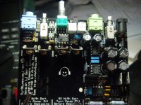
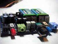
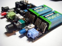
I finished building my O2's (two of them), and am very pleased with the results. The boards are very nice, the build was easy, and the sound is excellent. Definitely way better than my old cmoy. Output offset voltages measured 2.9mV and 2.7mV, so excellent. Just waiting for front panels. I may need to order more boards and parts, as friends now want their own!
Here are a couple of pics:
Here are a couple of pics:
Attachments
I just finished putting my amp together and testing was going okay.
However, I'm having some issues with the low battery circuit.
With no headphones connected, disconnecting the battery in position Bat1 produces a DC spike up to around 2.5 volts then settles down to around .3 volts. When removing Bat2 the spike hits around 6 volts and settles around .25 volts. I'm assuming I managed to kill one of the components but was wondering which one was the most likely suspect.
I did substitute FK24X7R1E105K TDK Multilayer Ceramic Capacitors (MLCC) - Leaded for C1 as I had some on hand but when reading the data sheets they appeared to be pretty much the same.
I just finished putting my amp together and testing was going okay.
However, I'm having some issues with the low battery circuit.
With no headphones connected, disconnecting the battery in position Bat1 produces a DC spike up to around 2.5 volts then settles down to around .3 volts. When removing Bat2 the spike hits around 6 volts and settles around .25 volts. I'm assuming I managed to kill one of the components but was wondering which one was the most likely suspect.
I did substitute FK24X7R1E105K TDK Multilayer Ceramic Capacitors (MLCC) - Leaded for C1 as I had some on hand but when reading the data sheets they appeared to be pretty much the same.
Wow, yeah, that's some serious DC there. Be careful until you have that resolved--though I personally can't be of any help.
I just finished putting my amp together and testing was going okay.
However, I'm having some issues with the low battery circuit.
With no headphones connected, disconnecting the battery in position Bat1 produces a DC spike up to around 2.5 volts then settles down to around .3 volts. When removing Bat2 the spike hits around 6 volts and settles around .25 volts. I'm assuming I managed to kill one of the components but was wondering which one was the most likely suspect.
I did substitute FK24X7R1E105K TDK Multilayer Ceramic Capacitors (MLCC) - Leaded for C1 as I had some on hand but when reading the data sheets they appeared to be pretty much the same.
How long is the spike? This may be how it actually looks before the low battery circuit kicks in, and since the voltages are down below .5V once it kicks in, it is probably fine.
I'm putting my O2 together this afternoon and recalling some of the posts regarding the build. I found this one, and am using the p/n163-7620-E, but it isn't making sense to me. I also recall a post mentioning a backward capacitor silkscreen, and am not finding that either (the post or the silkscreen error). Any clarification would be greatly appreciated.Originally Posted by MrSlim
Check that the outside pin on the power connector isn't shorted to the case. NwAvGuy (RS) mentions cutting the outside pin off very close to the board, and you'll need to do it before soldering to get it short enough, to prevent a short to the case.
edit: I should add, I don't have the B2 case yet to better eyeball the situation.
Last edited:
Ah ha... RS has noted on the schematic, "Trim J2 Pin5 (outer pin) Very Close To Board" so that is no longer an issue for me. For those planning a future build, it might be worth it to take a moment before power-on testing to insert the stuffed PCB into the B2, then take a resistance measurement from the case to pin 1 of P1 (the square pad closest to the front).
Oh yeah... the resistance should be ~10k ohms, if I'm not mistaken. Anything close to zero is not good!
Oh yeah... the resistance should be ~10k ohms, if I'm not mistaken. Anything close to zero is not good!
Last edited:
From disconnection of the battery until it settles down takes one to two seconds.
I plugged in a pair of junk earbuds to see if that made a difference and heard a loud snapping noise each time with them about a foot and a half away from my ears.
Unless you happen to drop the the O2 hard enough to dislodge one of the batteries (in which case you are likely to have other physical problems...) it is unlikely that you are going to see a failure mode that is going to cause this kind of spike. RocketScientist has designed the protection circuit to shut down the amp when the output of the batteries becomes unequal, for whatever reason, and in most cases, the voltage drop is never going to be as immediate as a total disconnection of a battery when its powered on..
I'm putting my O2 together this afternoon and recalling some of the posts regarding the build. I found this one, and am using the p/n163-7620-E, but it isn't making sense to me. I also recall a post mentioning a backward capacitor silkscreen, and am not finding that either (the post or the silkscreen error). Any clarification would be greatly appreciated.
edit: I should add, I don't have the B2 case yet to better eyeball the situation.
I think you were dreaming about the backward capacitor silkscreen..
")
I haven't seen anything like that, and I've been following this very closely..
LOL Probably so. Thanks.I think you were dreaming about the backward capacitor silkscreen..
I haven't seen anything like that, and I've been following this very closely..
It's coming along fine. Mostly done except for the DIPs and FETs. And my volume pot is on backorder so I'll have to jumper it temporarily.
Just completed my board tonight. Plugged it in, LED goes on, nothing blew up, so good so far. Plugged it into a source/headphones and no output at all. no static, no anything. Any clues on whats going on?
Hi:
Other than a basic smoke test (LED on, no smoke) have you done the basic tests? What is the measured voltage of your transformer? Transformer plugged in, power off, no batteries installed: what is the voltage across the battery terminals. Power turned on, what is the voltage across pins 4 and 8 on the IC sockets? What is the voltage across the electrolytic caps?
Thank you MrSlim. That made me feel safe enough to try the amp with music and better headphones. I will just make sure there is no way a battery can be disconnected during use. I could not hear anything that might suggest something is wrong enough to keep me from using it, although I will be paying close attention when the batteries start to get low.
All the other tests went great, including only 3-4mW of DC offset during normal use, so I will start enjoying the amp.
Thank you RS for a great and inexpensive amp.
All the other tests went great, including only 3-4mW of DC offset during normal use, so I will start enjoying the amp.
Thank you RS for a great and inexpensive amp.
You should be able to attach the batteries to the board with cable ties through the two (?) holes next to the battery spaces...
(I think there are two holes, I don't have a board or an O2 in front of me. But I believe thats how RocketScientist did it in one of the pictures on his site.)
Alternatively: Double sided foam tape should work.
In Germany you can also buy something called "Montageband" or "mounting tape".
I don't know if this is the right word in english, but its very much like a (1mm) thick piece of rubber that has adhesive on both sides.
It compensates not only uneven surfaces (no problem here) but it also stays flexible and doesn't become brittle over time.
That should allow even rough handling of the O2 without the batteries being a problem.
YMMV on the disassembly, you might damage your batteries or O2 when you try to take it apart... a little temperature (30 degrees Celsius) and it should be no problem to disassemble.
^If I were so inclined, I would print an actual-sized copy of the existing faceplate file onto heavy paper and use it as a template. Some good hole-making techniques were recently discussed in this thread. A hand drill can be used, it just requires more patience to get it right.
You're saying that it won't turn on at all, using batteries or AC power? No light at the LED? Have you gone through the "post build" testing steps on NwAvGuy's blog? Can you measure voltage at any of the test points he specifies?
It will probably be a long, slow process to find the issue, but it can be done.
@tschuss. Thanks for responding. I went through the complete "post build" testing steps and the amp worked beautifully until, I tried it in the case. I checked all potential chassis contact points before turning it on, but as soon as I did, the LED did not turn on, and I have no sound out of the headphones.
Today I restarted the testing steps and measured the following voltages at the caps listed below:
C10: 10.62 v
C17: 14.45 v
C18: 3.934 v
C8: 14.50 v
C16: 28.82 v
C21: 0.012 v
C1: 3.775 v
The readings clearly indicate that there is an issue in one of the rails. I just don't know what component(s) I should test next to determine what needs to be replaced. Please help.
I know this is ill advised, but I want to try my hand at building my own face plates. The issue is I don't have a drill press, just a hand drill. Has anybody tried to do it with a hand drill?
A reamer and a tapered round file do wonders for this type of work. I've done all of my front panels by hand, no issues (except for the amount of time spent). It is ill-advised by the people who can't do it or don't appreciate the "art"
Good luck! I should have mine finished as soon as this weekend
- Home
- Amplifiers
- Headphone Systems
- The Objective2 (O2) Headphone Amp DIY Project